Crossbeam structure of semitrailer and welding process thereof

A welding process and semi-trailer technology, applied in the substructure, welding equipment, manufacturing tools, etc., can solve problems such as welding errors, heavy girders, and component offsets, and achieve the effect of avoiding errors

Inactive Publication Date: 2019-02-22
石家庄金多利专用汽车有限公司
View PDF6 Cites 2 Cited by
  • Summary
  • Abstract
  • Description
  • Claims
  • Application Information

AI Technical Summary

Problems solved by technology

The semi-trailer girder structure provided by the present invention can reduce the manufacturing time of the girder, reduce the working intensity of employees, reduce the use of consumables required for the manufacture of the girder, reduce the cost, and improve the production efficiency. In the process of installing and welding all parts, the parts may be offset to a certain extent, resulting in a certain welding error

Method used


Image

  • Crossbeam structure of semitrailer and welding process thereof
  • Crossbeam structure of semitrailer and welding process thereof
  • Crossbeam structure of semitrailer and welding process thereof

Examples


Embodiment 1

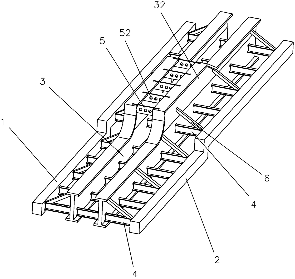
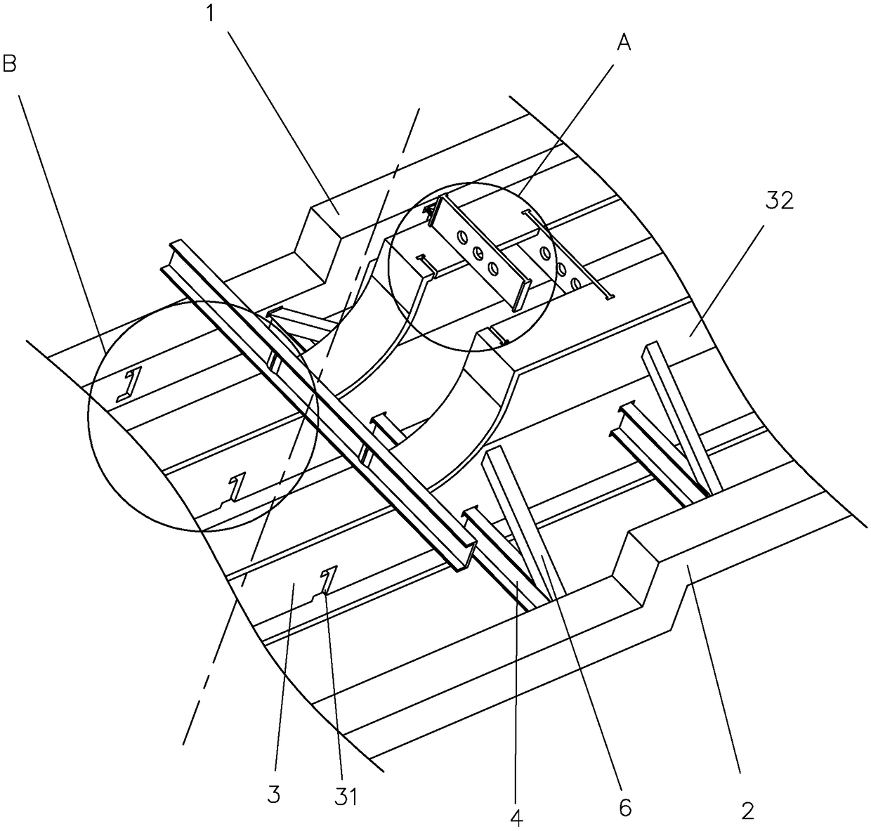
[0038] Embodiment 1: a kind of semi-trailer beam structure, such as figure 1 , 2 As shown, it includes a left wing plate 1 and a right wing plate 2, two webs 3 are arranged between the left wing plate 1 and the right wing plate 2, and a plurality of connecting plates with bow-shaped sections are also arranged between the left wing plate 1 and the right wing plate 2 4. In addition, each web 3 is provided with a plurality of arcuate insertion holes 31 , and the two ends of each connecting plate 4 respectively pass through each insertion hole 31 and are fixed on the side walls of the left wing 1 and the right wing 2 .

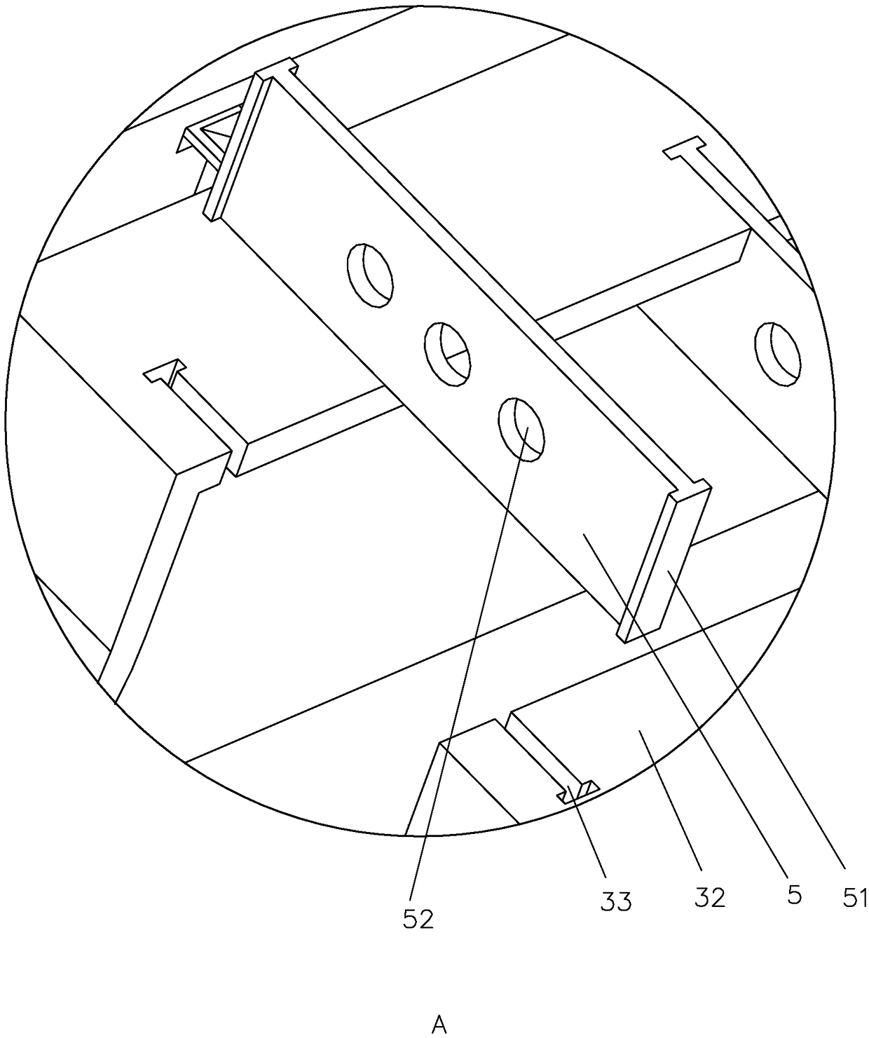
[0039] like figure 2 , 3 As shown, an extension plate 32 is integrally connected to the middle of each web 3, a plurality of T-shaped slots 33 are respectively provided on the opposite side of each extension plate, and a positioning plate 5 is arranged between each extension plate 32 for positioning The two ends of the plate 5 are respectively fixedly connecte...

Embodiment 2

[0043] Embodiment 2: a kind of semi-trailer girder welding process, its welding process comprises the following steps:

[0044] S1, align and place the two ends of the two webs 3 and keep them parallel, then insert the two ends of each positioning plate 5 into the T-shaped slot 33 of each web 3, and at the same time make the clamping plate 51 clamp into the T-shaped slot 33;

[0045] S2, spot welding the two ends of each positioning plate 5 respectively;

[0046] After the web 3 is aligned and placed and the positioning plate 5 is inserted into each T slot, at this moment the clamping plate 51 will be stuck in the T-shaped slot 33, and the two ends of the positioning plate 5 are spot welded and fixed on the T slot. On the web 3, the two webs 3 will be relatively fixed, so as to prevent the web 3 from moving when installing other parts on the web 3 later, so that other parts cannot be accurately installed on the designated position.

[0047] S3, each connecting plate 4 is respe...


PUM


Abstract

The invention discloses a crossbeam structure of a semitrailer and a welding process thereof and belongs to the field of crossbeam structures of vehicles. The technical scheme is as follows: the structure comprises a left wing plate and a wing web plate, two web plates are arranged between the left wing plate and the right wing plate, a plurality of connecting plates with arched sections are arranged between the left wing plate and the right wing plate, a plurality of arched insertion holes are formed in each web plate, two ends of each connecting plate separately penetrate the insertion holesand are fixed to the side walls of the left wing plate and the right wing plate, an extension plate is integrally connected to the middle of each web plate, a plurality of T-shaped slots are separately formed in opposite side of each extension plate, a positioning plate is arranged between two extension plates, two ends of each positioning plate are fixedly connected to a clamping plate verticalto the positioning plate, separately, and two ends of each positioning plate and the clamping plate stretch into the T-shaped slots, separately. Therefore, the position of a part of the crossbeam is determined conveniently for welding, so that a certain error can be avoided.

Description

technical field [0001] The invention relates to the field of vehicle girder structures, in particular to a semi-trailer girder structure and a welding process thereof. Background technique [0002] At present, semi-trailers have occupied a major position in my country's transportation industry, and the performance of the semi-trailer's beam is related to the performance of the semi-trailer. The semi-trailer frame is the main load-bearing part of the semi-trailer body, and the volume and weight of the semi-trailer frame are relatively large, which is particularly important in the processing of the semi-trailer frame. [0003] The Chinese patent with the publication number CN103192189A discloses a semi-trailer beam structure and its welding process. It includes an upper wing, a lower wing and a web, and the upper wing, the lower wing and the web are vertically assembled, and the web deviates from The center lines of the upper and lower wings are provided with welding seam pos...

Claims


Application Information

Patent Timeline
IPC IPC(8): B62D21/20B23K31/02
CPCB23K31/02B62D21/20
Inventor 赵文龙赵红卫
Owner 石家庄金多利专用汽车有限公司
Why Eureka
Try Eureka