Cupped drink cap-pressing machine
A technology for capping machines and beverages, which is applied in the field of food packaging and processing, can solve the problems of inconvenient capping and capping, affecting the process, and unstable lids, ensuring consistency and continuity, and reducing the time for adjusting the machine. , to ensure continuous and uninterrupted effects
- Summary
- Abstract
- Description
- Claims
- Application Information
AI Technical Summary
Problems solved by technology
Method used
Image

Examples
Embodiment Construction
[0034] The content of the present invention will be described in further detail below in conjunction with the accompanying drawings and specific embodiments.
[0035] Example:
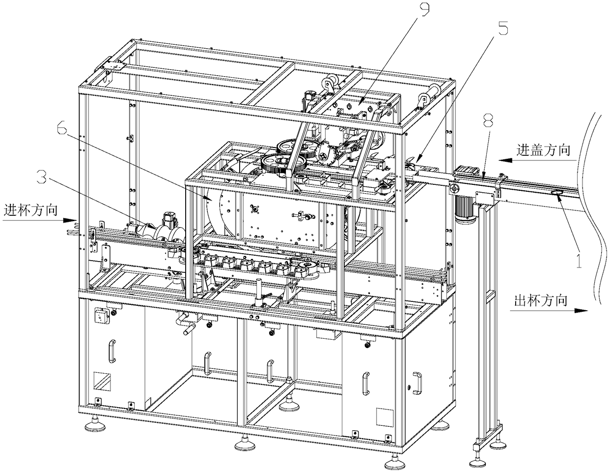
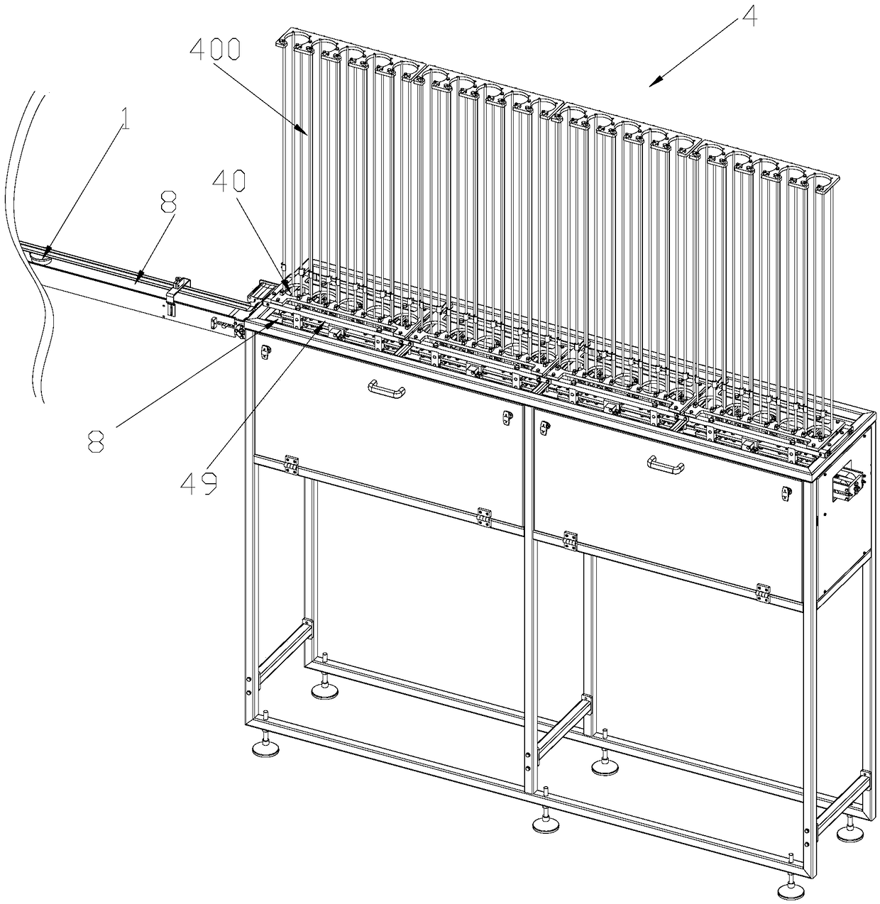
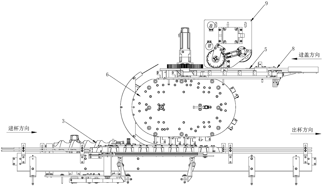
[0036] see figure 1 with image 3 As shown, a capping machine for cup-packed drinks has a capping station and a capping station, which are used to press the cup lid 1 onto the cup 2 at the capping station, including conveying the cup 2 to the pressing station. The sub-cup assembly 3 of the cover station also includes: a sub-cap assembly 4, which is used to be compatible with cup covers 1 of different heights and sends the cup cover 1 to the conveyor belt 8; The conveyed cup lids 1 are output to the cap grabbing station after sorting the constant spacing; the cap grabbing claw assembly 6 is used to take away the cup lids 1 with the trimmed spacing and run them to the capping station and then cover them on the cup 2; separate the lids The assembly 4 is connected with the synchronous cap feeding assembly...
PUM
 Abstract
Description
Claims
Application Information
 - Generate Ideas
- Intellectual Property
- Life Sciences
- Materials
- Tech Scout
- Unparalleled Data Quality
- Higher Quality Content
- 60% Fewer Hallucinations
Browse by: Latest US Patents, China's latest patents, Technical Efficacy Thesaurus, Application Domain, Technology Topic, Popular Technical Reports.
© 2025 PatSnap. All rights reserved.Legal|Privacy policy|Modern Slavery Act Transparency Statement|Sitemap|About US| Contact US: help@patsnap.com