
Spiral conveyor with blade wear-resistant layer capable of being compensated

A technology of screw conveyor and wear-resistant layer, applied in packaging and other directions, can solve the problems of reduced working efficiency of screw conveyor, insufficient screw conveying capacity, inability to replace, etc., and achieve the effects of convenient maintenance, low cost and high efficiency

Pending Publication Date: 2019-02-22
JIANGSU KAIGONG TUNNEL MACHINERY
View PDF0 Cites 2 Cited by
  • Summary
  • Abstract
  • Description
  • Claims
  • Application Information

AI Technical Summary

Problems solved by technology

Therefore, the working efficiency of the screw machine has been declining, and in actual work, the construction period is often delayed due to insufficient screw conveying capacity.
[0004] In addition, after the existing screw machine blades are worn out, they cannot be replaced on the general construction site. They need to be returned to the factory. The technical engineer will inspect and measure the wear condition, calculate the wear amount according to the original design drawings, and then make the repair process and draw required drawing

Method used


Image

  • Spiral conveyor with blade wear-resistant layer capable of being compensated
  • Spiral conveyor with blade wear-resistant layer capable of being compensated
  • Spiral conveyor with blade wear-resistant layer capable of being compensated

Examples


Embodiment Construction

[0026] A preferred embodiment of the present invention will be described in detail below in conjunction with the accompanying drawings. However, the scope of protection of the present invention is not limited to the following examples, that is, any simple equivalent changes and modifications made based on the patent scope of the present invention and the content of the description are still within the scope of the patent of the present invention.

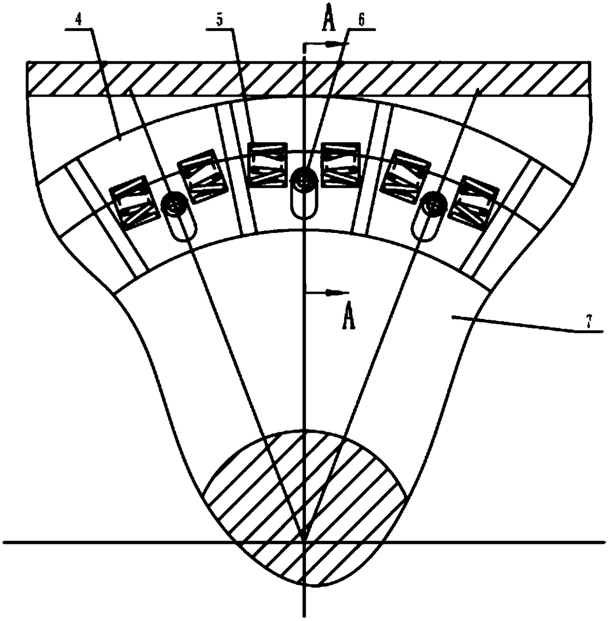
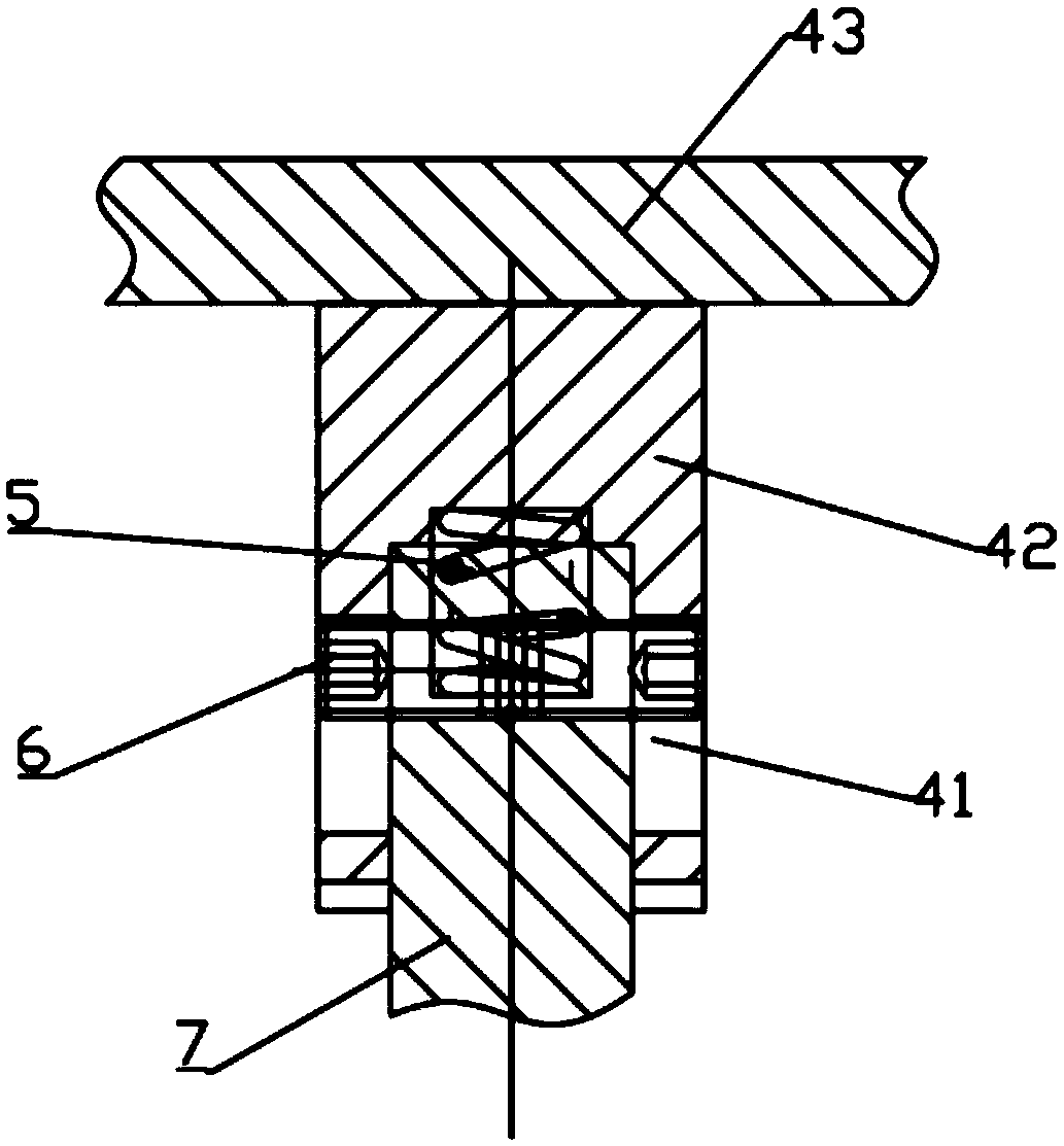
[0027] refer to Figure 1-3 , is a screw conveyor with compensable blade wear-resistant layer according to the present invention, including a cylinder body 2, a screw rod 1 pierced in the cylinder body, and a screw conveyor fixed to the outer end of the cylinder body and driven with the screw rod Connected driving device 3, the outer surface of the screw rod is fixed with a helical blade 7 wound along the axial direction of the screw rod 1; the driving device drives the screw rod to rotate in the cylinder to drive the required mediu...


PUM


Abstract

The invention discloses a spiral conveyor with a blade wear-resistant layer capable of being compensated. The spiral conveyor comprises a cylinder body, a screw rod and a driving device, wherein the screw rod is arranged in the cylinder body in a penetrating mode, the driving device is fixed to the outer end of the cylinder body, and spiral blades are fixed on the outer side surface of the screw rod; a plurality of limiting screws are sequentially fixed on the portions, located inside the cylinder body, of the spiral blades and close to the outer end of the cylinder body, each limiting screw is provided with a blade wear-resistant block, each blade wear-resistant block is provided with a movable limiting groove, the inner end of each blade wear-resisting block sleeves outside the corresponding limiting screw of the spiral blade, the limiting screws are arranged in the movable limiting grooves, and a thrust spring is arranged between each blade wear-resistant block and the outer end ofthe corresponding spiral blade. According to the spiral conveyor, when the wear-resistant blocks are abraded, the wear-resistant blocks can automatically exit through the thrust springs, so that the abrasion loss is compensated, and not only is the service life of the spiral blade greatly prolonged and the stable working efficiency can be kept, but also the abrasion-resistant blocks can be directly replaced on the construction site when the wear-resistant blocks are damaged.

Description

technical field [0001] The invention belongs to the technical field of shield machine equipment, and in particular relates to a screw conveyor, in particular to a screw conveyor with a compensable blade wear-resistant layer. Background technique [0002] The earth pressure balance shield machine is equipped with a screw conveyor, referred to as the screw conveyor. The function of the screw conveyor is to transport the muck excavated by the cutter head from the soil bin to the shield body, and then transport it to the ground through the supporting transportation system. The ability of the screw machine to transport the muck will directly affect the excavation efficiency of the shield machine. The blade on the screw rod of the screw machine is an important rotating part of the screw machine, and it is also a part that is easy to wear. The wear of the blade often reduces the conveying efficiency of the screw machine to the muck. [0003] At present, the blades of the screw con...

Claims


Application Information

Patent Timeline
Patent Type & Authority Applications(China)
IPC IPC(8): B65G33/26
CPCB65G33/26B65G2207/48
Inventor 苏延奇徐昊朗丁少华
Owner JIANGSU KAIGONG TUNNEL MACHINERY
Learn More