Yarn finishing equipment

A yarn and equipment technology, applied in the field of yarn finishing equipment, can solve the problems of lack of counting function, insufficient flexibility, error-prone memory, etc., achieve good connection and power transmission effects, ensure work efficiency, and increase contact area Effect

Inactive Publication Date: 2019-02-22
德清县金丝源纺织品有限公司
View PDF6 Cites 0 Cited by
  • Summary
  • Abstract
  • Description
  • Claims
  • Application Information

AI Technical Summary

Problems solved by technology

Before the yarn is sampled on the sample machine, it needs to be sorted into yarns with a certain quantity and length. The existing device for sorting the yarn for the sample machine is to manually shake a rotating rod installed on the bracket to drive The cylindrical scaffolding on the rotating rod rotates, so that the bobbin or skein is wound on the cylindrical scaffolding to obtain a certain length and quantity of yarn; however, the shape of the cylindrical scaffolding is fixed, and the circumference of the outer circumference cannot be changed. Adjustment can only wind the yarn with a limited length, which is not flexible enough; it also lacks a counting device. When the operator rotates the cylindrical scaffolding for yarn arrangement, he needs to constantly memorize the number of rotations, which is very labor-intensive and labor-intensive. Brain power, when the number of rotations is large, human memory is prone to errors, which will cause inconvenience to subsequent operations; the bracket is a fixed frame, which can only play a limited supporting role, and cannot be adjusted according to the needs of the operator. Very inflexible; In addition, when the operator holds the handle glove and rotates it, due to long-term operation, the hands are prone to sweating, and the handle glove is relatively smooth, and the friction force is small. It is easy to slip on the surface, which will affect the work efficiency
[0004] Therefore, the existing yarn finishing device for the sample machine has the problems that the length of the yarn cannot be adjusted, the flexibility is not enough, the counting function is lacking, the height cannot be adjusted, and it is easy to slip

Method used


Image

  • Yarn finishing equipment
  • Yarn finishing equipment
  • Yarn finishing equipment

Examples


Embodiment Construction

[0045] The present invention will be further described below in conjunction with the accompanying drawings and embodiments, but not as a basis for limiting the present invention.

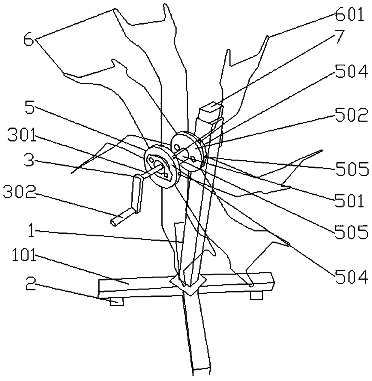
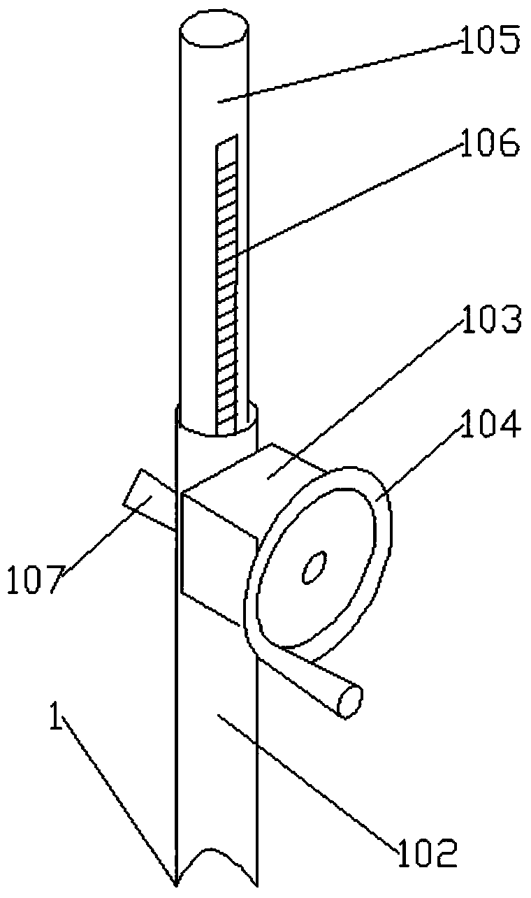
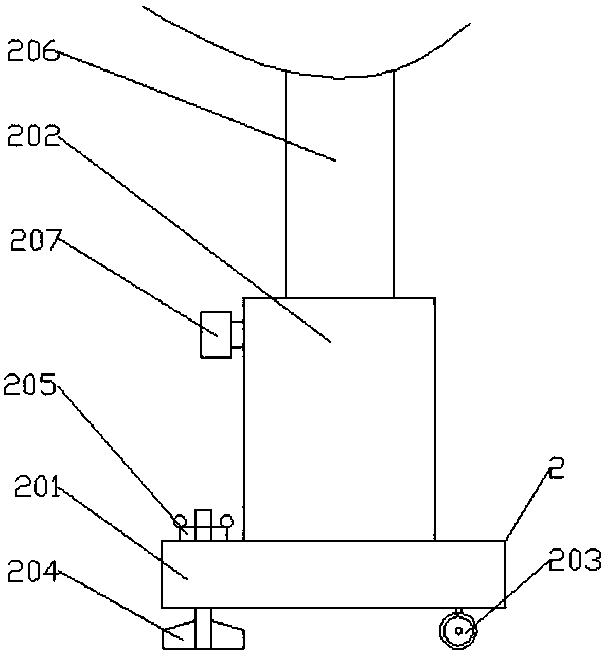
[0046] Such as figure 1 , figure 2 , Figure 4 , Figure 5 , Image 6 , Figure 7 , Figure 8 , Figure 9 , Figure 10 , Figure 11 , Figure 12 , Figure 13 , Figure 14 with Figure 15The yarn finishing equipment shown includes a lifting frame 1, a rotating mechanism 3 arranged on the upper part of the lifting frame, a connecting piece 4 arranged on the rotating mechanism, a wheel assembly 5 arranged on the rotating mechanism, and a wheel assembly arranged on the rotating mechanism. Several shelving components 6 and the mechanical counting mechanism 7 arranged on the top of the lifting bracket, the connectors are connected with the mechanical counting mechanism; the lifting bracket includes a base 101 and a support cylinder 102 arranged on the base, and the support cylinder is provide...


PUM


Abstract

The invention relates to the technical field of textile machinery equipment, and particularly discloses yarn finishing equipment which comprises a lifting support, a rotating mechanism, a connecting element, a wheel plate assembly, a shed frame assembly and a mechanical counting mechanism. The lifting support comprises a base and a supporting cylinder, and a gearbox is arranged on the supporting cylinder. The rotating mechanism comprises a Z-shaped rotating rod and a silicone rubber handle cover. The wheel plate assembly comprises a rotating cylinder, first wheel plate covers, and second wheelplate covers arranged on the first wheel plate covers. A supporting frame is composed of a first connecting rod, a second connecting rod, a third connecting rod, a fourth connecting rod, a fifth connecting rod, a sixth connecting rod, a seventh connecting rod, an eighth connecting rod, a ninth connecting rod, a tenth connecting rod and a eleventh connecting rod which are connected in sequence. The mechanical counting mechanism comprises a cover shell, a counting shaft, a carry shaft, counting plates, carry gears and end face supporting teeth. The yarn finishing equipment has the advantages ofadjustable yarn length, good flexibility, counting function, adjustable height and no easy slipping.

Description

technical field [0001] The invention relates to the technical field of textile machinery and equipment, in particular to a yarn finishing equipment. Background technique [0002] Textile machine is the full name of the tool that processes thread, silk, hemp and other raw materials into silk thread and then weaves cloth. Textile machine has a long history, which can be traced back to the Neolithic Age at the earliest. , Pedal looms, mechanical looms, and CNC looms. The function of the textile machine is more and more comprehensive, and the textile efficiency is also higher and higher. [0003] Before the enterprise produces textile products in the workshop according to the customer's requirements, it needs to make samples on the sample machine to check whether the products made by the sample machine meet the production requirements. If the small sample products meet the requirements, they will carry out mass production in the workshop. If the sample product does not meet th...

Claims


Application Information

Patent Timeline
Patent Type & Authority Applications(China)
IPC IPC(8): B65H54/44B65H54/547B65H54/70B65H54/72B65H61/00
CPCB65H54/44B65H54/547B65H54/70B65H54/72B65H61/00B65H2701/31
Inventor 杨锋
Owner 德清县金丝源纺织品有限公司
Why Eureka
Try Eureka