

Non-Newtonian fluid speed limiter and speed limiting belt thereof
A non-Newtonian fluid and speed limiter technology, which is applied to roads, road signs, traffic signals, etc., can solve the problems of rigid speed reduction belt speed limit setting, inability to adjust speed limit belt speed limit performance, inappropriateness, etc.
Inactive Publication Date: 2019-02-22
河北科创商务信息咨询有限公司
View PDF0 Cites 8 Cited by
- Summary
- Abstract
- Description
- Claims
- Application Information
AI Technical Summary
Problems solved by technology
[0006] Most of the current acceleration belts are rigid protrusions such as hard rubber, cast iron, and cement. As long as the passing vehicles must be crushed, for some unnecessary all-weather deceleration sections, there are also disadvantages of the speed bumps on the very frequently used sections. It is more beneficial, but it is obviously inappropriate not to set it; but in this way, there will still be bumps and ups and downs for vehicles below the speed limit. For rigid speed bumps, the speed limit setting that adapts to the road conditions cannot be achieved. Adjust the speed limit performance of the speed belt, these are the two problems we are currently facing
Method used
View moreImage
Smart ImageViewing Examples

Examples
Embodiment 2
[0052] Compared with Embodiment 1, the resistance plate 4 is a cone, and Embodiment 2 is an orifice plate. The resistance plate 4 is an orifice plate, and the body of the resistance plate 4 is uniformly provided with flow holes 43. The resistance plate 4 A through hole 44 is provided in the center.
Login to View More PUM
 Abstract
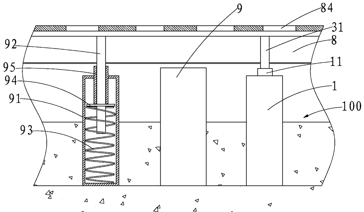
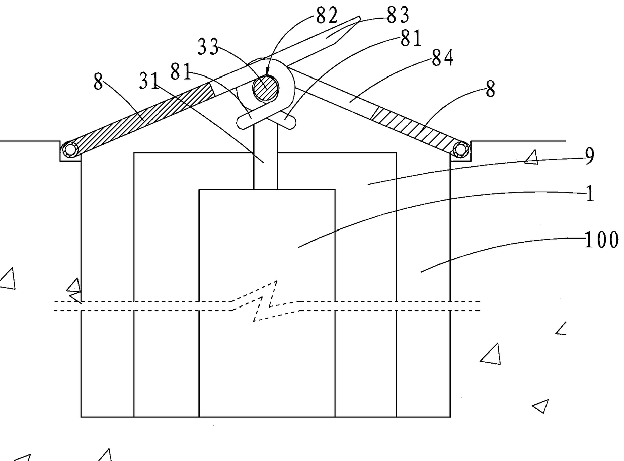
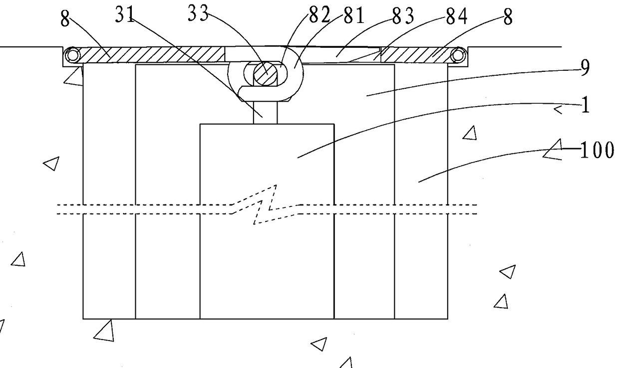
The invention relates to a non-Newtonian fluid speed limiter. The non-Newtonian fluid speed limiter comprises multiple non-Newtonian fluid speed limiter bodies arranged in a groove, a pressing rod inseries connection with bottom ends of multiple pressure pushing rods and two cover plates buckled on an opening of the groove; one sides of the cover plates are hinged to the top edge of the groove, hook tongue plates are arranged on the other sides of the cover plates at intervals, the hook tongue plates of the two cover plates are embedded in a staggered manner, the hook tongue plates of the twocover plates extend reversely to form a pressure groove hole in a defined manner, and a pressing rod is embedded in the pressure groove hole. According to the speed limiter, through limiting of the descending speed of the cover plates, barrier of wheels can be achieved, the action that the wheels press the cover plates downwards can be transmitted by the pressure push rods, once the flow speed ofnon-Newtonian fluid is too fast, a resistance plate can be stopped, the flow speed and the flow of the non-Newtonian fluid are limited, descending of a thrust plug is limited, the descending speed ofthe cover plates can be limited, and the speed limiting effect is achieved. When the vehicle speed is not fast, the non-Newtonian fluid smoothly passes through the resistance plate, the cover platesare perpendicular to the road face, and a car can smoothly pass through a speed reduction belt.
Description
technical field [0001] The invention relates to the technical field of deceleration belts, and relates to a non-Newtonian fluid speed governor and a speed limiting belt thereof. Background technique [0002] The deceleration belt realizes deceleration by affecting the driver's driving psychology. When the vehicle passes the deceleration belt at a high speed, the severe vibration will be transmitted from the tire to the driver through the body and seat, and the vertical curve can generate a vertical acceleration and strong physiological stimulation (including vibration stimulation and visual stimulation) and psychological stimulation. Physiological stimulation promotes a strong sense of discomfort for the driver, while psychological stimulation deepens the driver's doubts about safety and further reduces the driver's sense of safety on the road environment. Usually, the driver thinks that the greater the degree of discomfort, the less safe the vehicle is, that is, the less ...
Claims
Login to View More Application Information
Patent Timeline
 IPC IPC(8): E01F9/529
CPCE01F9/529
Inventor王阳
Owner河北科创商务信息咨询有限公司