Out-of-control blowout well head device reset method
A technology of wellhead device and flange is applied in the field of wellhead device reset for out-of-control blowout, which can solve the problems of low efficiency and high risk, and achieve the effects of reducing operation time, reducing the number of operations close to the wellhead, and improving the efficiency of rush-loading wellhead operations.
- Summary
- Abstract
- Description
- Claims
- Application Information
AI Technical Summary
Problems solved by technology
Method used
Image
Examples
Embodiment 1
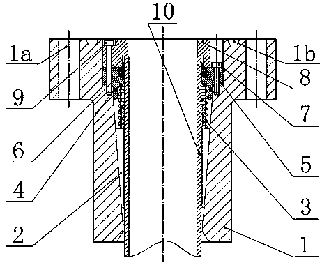
[0034] As a preferred embodiment of the present invention, it discloses a method for resetting the wellhead device for blowout out of control, designing an integrated bottom flange for oil and gas well blowout out of control rescue, connecting it to the lower part of the new wellhead device, and resetting it with the wellhead The device pressurizes them into the optical sleeve 10 to realize clamping and sealing of the sleeve 10 .
[0035] When cutting the casing 10, use a beveling machine to cut off the casing 10, and at the same time pour out the bevel on the top surface of the casing 10, so that the integrated oil and gas well blowout out of control emergency bottom flange can be inserted into the casing 10, and the emergency bottom flange can be avoided. Damage to seals.
[0036] The bottom flange for out-of-control blowout rescue can be contracted or expanded according to the size of the installed casing 10. The spring 3 gives a fixed pre-tightening force to the slips 2. T...
Embodiment 2
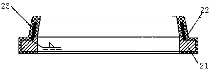
[0039] As another preferred embodiment of the present invention, it discloses an integrated oil and gas well blowout out-of-control bottom flange, which includes: body 1, slips 2, spring 3, O-ring 4, spring pressure block 5, Skeleton sealing ring 6, anti-settling positioning block 8, the body 1 is provided with a conical inner cavity with a large upper part and a smaller lower part, the slips 2 are installed in the conical inner cavity and self-locking, and the middle part of the slips 2 is provided with a casing 10 passes through and matches the opening, the spring 3 is set on the upper part of the slip 2 and the spring 3 is pre-compressed by the spring pressure block 5, the O-shaped sealing ring 4 is installed on the outer ring of the spring pressure block 5, and the spring pressure block 5 is fixed on the body 1, the skeleton sealing ring 6 is installed in the inner ring of the spring pressing block 5, the anti-sinking positioning block 8 is placed on the upper part of the s...
Embodiment 3
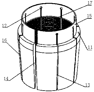
[0044]As another preferred embodiment of the present invention, the disclosed slip 2 includes an upper part and a lower part that are fixedly connected together or integrally formed, the shape of the lower part is a cone 16, the upper part is larger and the lower part is smaller, and the upper part is a cylindrical shape 15. There is a step 11 at the intersection of the lower part of the cylinder 15 and the cone 16. The inner diameter of the slip 2 is processed with evenly distributed teeth 17, and the inner diameter of the upper light hole is larger than the inner diameter of the teeth 17.
[0045] The shape of the lower part is a cone 16, the upper part is larger and the lower part is smaller, and the taper angle of the conical surface satisfies the self-locking function. The upper shape is a cylinder 15, and there is a step 11 at the intersection of the bottom of the cylinder 15 and the cone 16. The surface of the cone 16 and the step 11 is used to fix the preload spring 3, ...
PUM
 Abstract
Description
Claims
Application Information
 - R&D
- Intellectual Property
- Life Sciences
- Materials
- Tech Scout
- Unparalleled Data Quality
- Higher Quality Content
- 60% Fewer Hallucinations
Browse by: Latest US Patents, China's latest patents, Technical Efficacy Thesaurus, Application Domain, Technology Topic, Popular Technical Reports.
© 2025 PatSnap. All rights reserved.Legal|Privacy policy|Modern Slavery Act Transparency Statement|Sitemap|About US| Contact US: help@patsnap.com


