
Differential pressure type constant pressure venting valve for oil exploitation

A technology of oil exploitation and differential pressure, applied in safety valves, balance valves, valve devices, etc., can solve problems such as intake pipe icing and intake pipe blockage, and achieve the effects of cost reduction, equipment efficiency improvement, and parts reduction

Pending Publication Date: 2019-02-22
江汉油田兴亚工矿配件潜江有限公司
View PDF0 Cites 0 Cited by
  • Summary
  • Abstract
  • Description
  • Claims
  • Application Information

AI Technical Summary

Problems solved by technology

[0004] The present invention proposes a pressure-difference type constant-pressure release valve for petroleum exploitation, which solves the problem in the prior art that the cold air generated during the release process freezes the intake pipe and causes blockage of the intake pipe

Method used


Image

  • Differential pressure type constant pressure venting valve for oil exploitation
  • Differential pressure type constant pressure venting valve for oil exploitation

Examples


Embodiment Construction

[0031]The technical solutions in the embodiments of the present invention will be clearly and completely described below in conjunction with the embodiments of the present invention. Apparently, the described embodiments are only some of the embodiments of the present invention, not all of them. Based on the embodiments of the present invention, all other embodiments obtained by persons of ordinary skill in the art without creative efforts fall within the protection scope of the present invention.

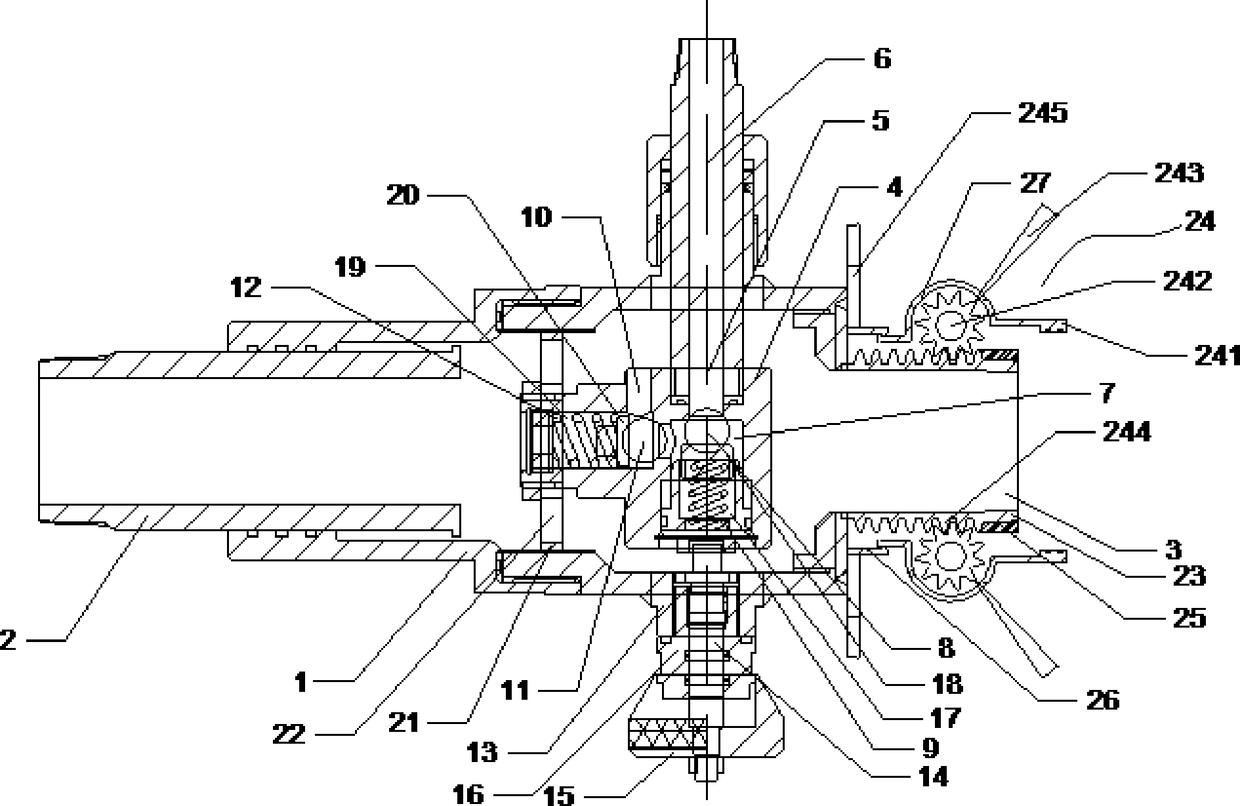
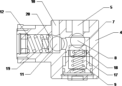
[0032] Such as Figure 1-2 As shown, the present invention proposes a pressure difference constant pressure release valve for oil exploitation,

[0033] It includes a valve body 1, one end of the valve body 1 is provided with an upper joint 2, the other end of the valve body 1 is provided with a lower joint 3, the valve body 1 is provided with a valve core 4, and the valve core 4 is provided with an air inlet 5, and the valve core 4 is provided with an air inlet 5. The air port 5 ...


PUM


Abstract

The invention belongs to the technical field of oil exploitations, and provides a differential pressure type constant pressure venting valve for oil exploitation. The differential pressure type constant pressure venting valve for oil exploitation comprises a valve body, wherein an upper contact is arranged on one end of the valve body; a lower contact is arranged on the other end of the valve body; a valve element is arranged in the valve body; an air inlet is formed in the valve element; the air inlet communicates with one end of an air inlet pipe; the other end of the air inlet pipe penetrates through the valve body and communicates with the outside; a ventilating chamber is formed in the inner side of the valve element; the air inlet communicates with the ventilating chamber; a first valve ball is arranged in the ventilating chamber; the first valve ball abuts against the end, communicating with the ventilating chamber, of the air inlet through a first spring; an air outlet pipe isarranged on the valve element; one end of the air outlet pipe communicates with the ventilating chamber; and the other end of the air outlet pipe communicates with the outside of the valve element. Bymeans of the aforementioned technical scheme, the problem that the cold air generated by a deflation process causes the air inlet pipe frozen and blocked in the prior art is solved.

Description

technical field [0001] The invention belongs to the technical field of oil exploitation, and relates to an oil exploitation differential pressure constant pressure release valve. Background technique [0002] With the development of the economy and the progress of society, energy conservation has become an inevitable and social consensus. The associated gas produced in the oil field must also be fully recovered. [0003] At present, the oilfield control casing pressure uses a constant pressure gas release device, which is installed between the gas outlet of the oil well casing and the single well mixed transportation pipeline. When it reaches or falls below the set value, it will automatically shut down. The size of the valve body with this structure cannot be adjusted. Due to the inconsistent height of the oil well itself, it is extremely inconvenient to perform short-circuit processing on site. Associated gas cannot be collected; special tools are needed for pressure re...

Claims


Application Information

Patent Timeline
Patent Type & Authority Applications(China)
IPC IPC(8): F16K17/04
CPCF16K17/04
Inventor 韩铁龙马喜林晏雄清侯辉王辉邹强
Owner 江汉油田兴亚工矿配件潜江有限公司
Learn More