Supercharge Your Innovation With Domain-Expert AI Agents!

Pyrometer

A pyrometer and main body technology, applied in the field of temperature measurement, can solve the problems of inability to eliminate visible light interference, inconvenient installation, easy damage, etc., and achieve the effects of improving data reliability, maintaining stability, and convenient operation

Pending Publication Date: 2019-02-22
XIAN WEIMIKE AUTOMATIC CONTROL INSTR TECH
View PDF0 Cites 1 Cited by
  • Summary
  • Abstract
  • Description
  • Claims
  • Application Information

AI Technical Summary

Problems solved by technology

[0005] The purpose of the present invention is to overcome the shortcomings of the above-mentioned prior art, and provide a pyrometer, which adopts an integrated design, has the advantages of convenient disassembly and maintenance, ready-to-use, low operation and maintenance costs, and reduces human-induced errors. In the original split design, the optical fiber part is easily damaged, visible light interference cannot be ruled out during measurement, and the problem of inconvenient installation

Method used


Image

  • Pyrometer
  • Pyrometer
  • Pyrometer

Examples


specific Embodiment approach

[0030] It should be noted that the structures, proportions, sizes, etc. shown in the drawings attached to this specification are only used to match the content disclosed in the specification, for those who are familiar with this technology to understand and read, and are not used to limit the implementation of the present invention Any modification of the structure, change of the proportional relationship or adjustment of the size shall still fall within the scope of the technical content disclosed in the present invention without affecting the effect and purpose of the present invention. In the range.

[0031] At the same time, terms such as "upper", "lower", "left", "right", "middle" and "one" quoted in this specification are only for the purpose of description, and are not used to limit the present invention. The practicable scope, the change or adjustment of its relative relationship, without any substantial change in the technical content, shall also be regarded as the pr...

Embodiment 1

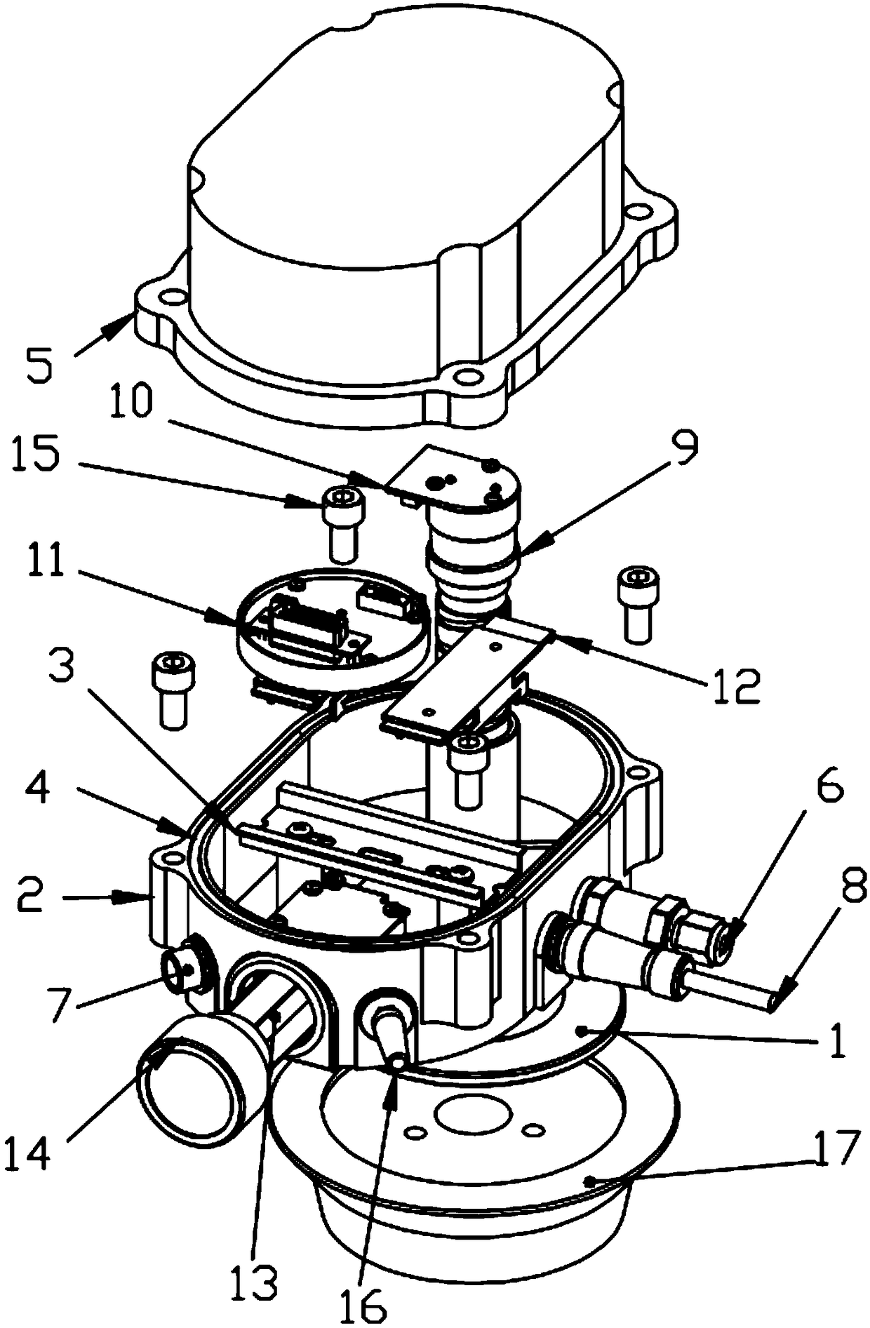
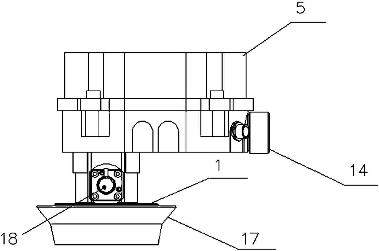
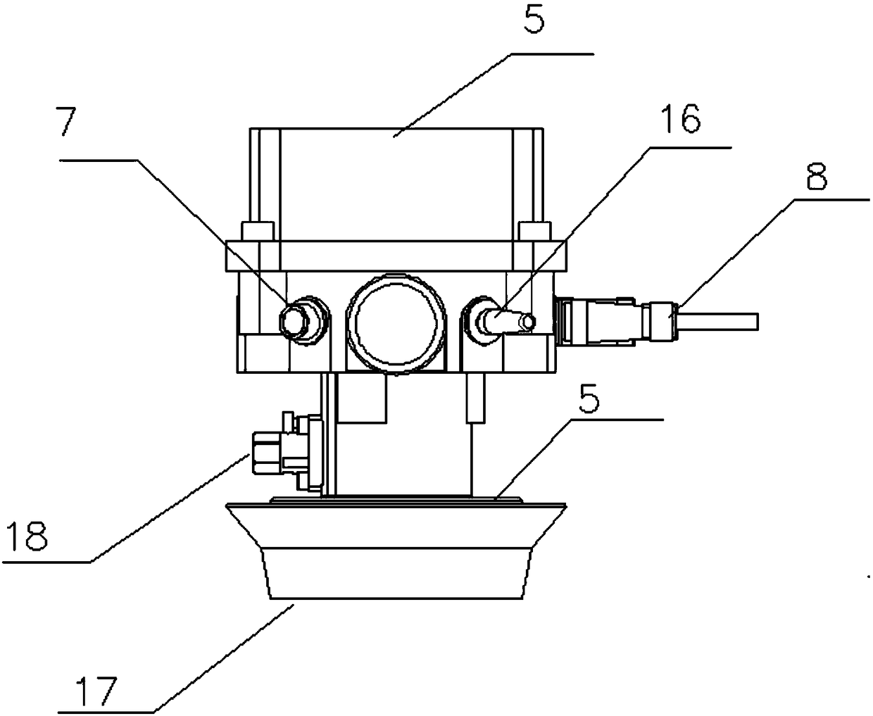
[0033] Such as figure 1 As shown, a pyrometer includes a main body 2 and an upper cover 5 connected together, and the edges where the main body 2 and the upper cover 5 are in contact are provided with lugs for screws 15 to pass through, that is, the main body 2 and the upper cover 5 are connected by bolts;

[0034] The main body 2 is equipped with an electrical guide rail 3, and the electrical guide rail 3 is provided with a conversion module 11 and an expansion board 12; the electrical guide rail 3 adopts a DN35 guide rail, and the use of guide rails is an installation method for industrial electrical components, and the installation supports this standard The electrical components can be easily clamped on the guide rail without fixing with screws, and the maintenance is also very convenient. The expansion board 12 is reserved for installing various conversion modules. For example, when a battery is used, a battery management module can also be installed on the expansion boa...


PUM


Abstract

The invention discloses a pyrometer comprising a main body and an upper cover connected together. A contact edge of the main body and the upper cover is provided with a lug for a screw to pass through. The main body is internally provided with an electric guide rail which is provided with a conversion module and an expansion board. The bottom of the main body is provided with a positioning hole, and an optical sensor and an optical lens assembly connected by a screw are inserted into the positioning hole. The periphery of the main body is circumferentially provided with an electronic antenna,a debugging port, a cable interface, a gas check valve and a battery compartment, the cable interface and the battery compartment are screwed to the main body, the battery compartment is provided witha detachable battery, and a furnace cover is set at the lower part of the main body. The pyrometer is an online pyrometer, an integrated design is adopted, and the pyrometer has the characteristics of convenient disassembly and maintenance, ready-to-use and easy maintenance.

Description

technical field [0001] The invention belongs to the technical field of temperature measurement, and in particular relates to a pyrometer. Background technique [0002] The coke oven is the most complicated kiln in the metallurgical industry, which is composed of multiple carbonization chambers and combustion chambers alternately arranged. [0003] The gas and air are preheated in the regenerator and enter the combustion chamber for combustion. The heat generated by the combustion is transmitted to the carbonization chamber through the furnace wall, and the coal undergoes high-temperature dry distillation in the carbonization chamber to form coke. The exhaust gas produced by combustion is discharged after being recovered by waste heat in the regenerator, and the flow direction of gas air and exhaust gas is exchanged at regular intervals. The heating process of the coke oven is a thermal process in which a single combustion chamber is intermittent and the whole furnace is con...

Claims


Application Information

Patent Timeline
Patent Type & Authority Applications(China)
IPC IPC(8): G01J5/00
CPCG01J5/0044
Inventor 王小雅王均利
Owner XIAN WEIMIKE AUTOMATIC CONTROL INSTR TECH
Features
  • R&D
  • Intellectual Property
  • Life Sciences
  • Materials
  • Tech Scout
  • Unparalleled Data Quality
  • Higher Quality Content
  • 60% Fewer Hallucinations
Learn More