
Field detection device suitable for bearing capacity of reinforced concrete beams and arranging method

A technology for on-site inspection of reinforced concrete beams, applied in the direction of applying stable tension/pressure to test the strength of materials, joists, girders, etc., which can solve the problems of other structures below, the inability to build floor supports, and the supports are susceptible to external disturbances, etc. , to achieve the effects of preventing tilting, saving manpower, and facilitating loading speed

Pending Publication Date: 2019-02-22
NANCHANG UNIV
View PDF8 Cites 8 Cited by
  • Summary
  • Abstract
  • Description
  • Claims
  • Application Information

AI Technical Summary

Problems solved by technology

[0003] The traditional setting method of the displacement meter support is as follows: the longitudinal steel pipe parallel to the beam and the horizontal steel pipe perpendicular to the beam are built into a "ladder"-shaped support, and several vertical steel pipes are arranged below to support the upper "ladder"-shaped support to form a The "cuboid" bracket has the characteristics of high, long and narrow as a whole, it is relatively unstable, the site situation is complicated, people move around frequently, and the traditional bracket is susceptible to external disturbances, resulting in inaccurate experimental data
There are certain restrictions on the use of brackets. In some cases, traditional floor brackets cannot be built, such as the inspection of the bottom beam of water buildings or other structures under the beam.
The commonly used stacking method is to stack sandbags on the beam body, and the load stacking and unloading process requires more manpower

Method used


Image

  • Field detection device suitable for bearing capacity of reinforced concrete beams and arranging method
  • Field detection device suitable for bearing capacity of reinforced concrete beams and arranging method
  • Field detection device suitable for bearing capacity of reinforced concrete beams and arranging method

Examples


Embodiment Construction

[0049] Below in conjunction with accompanying drawing and embodiment the present invention is further described:

[0050] see Figure 1-10 .

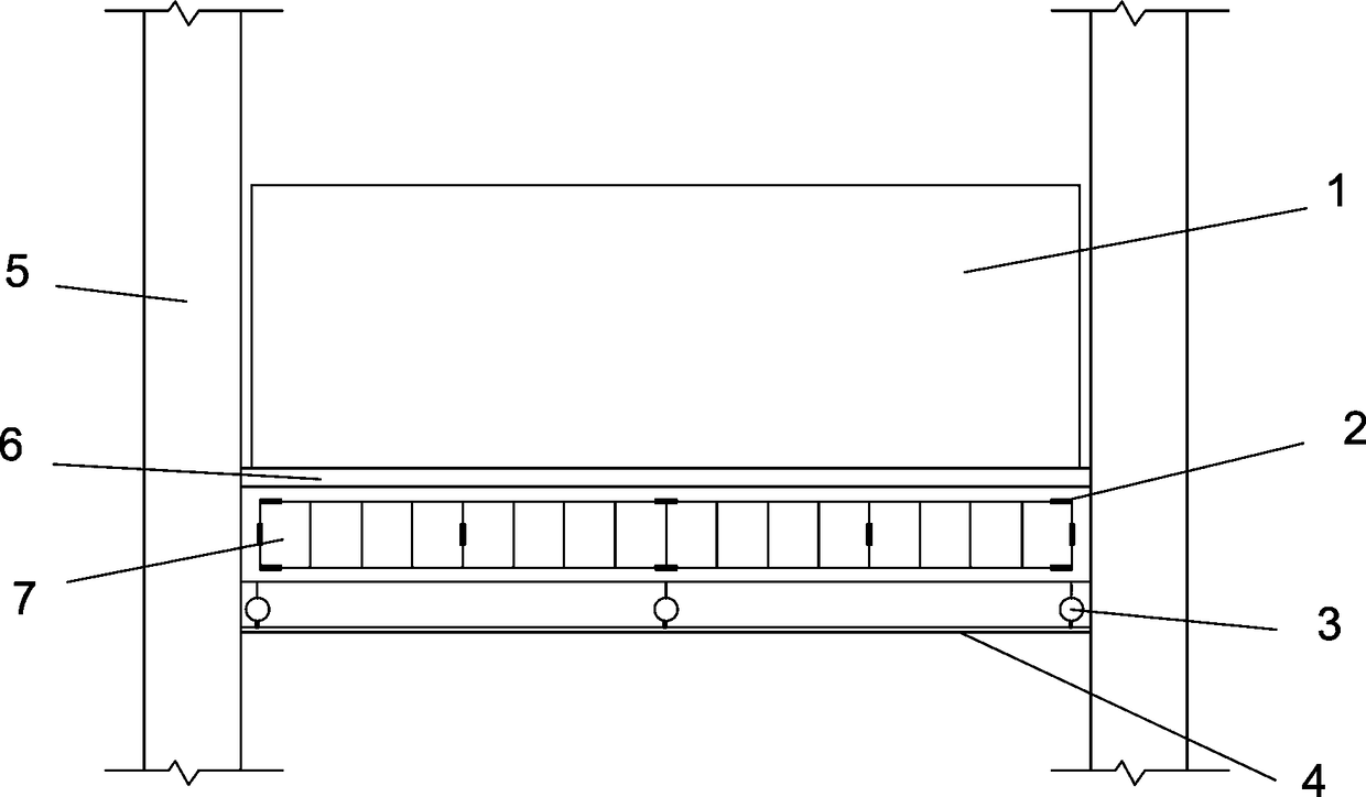
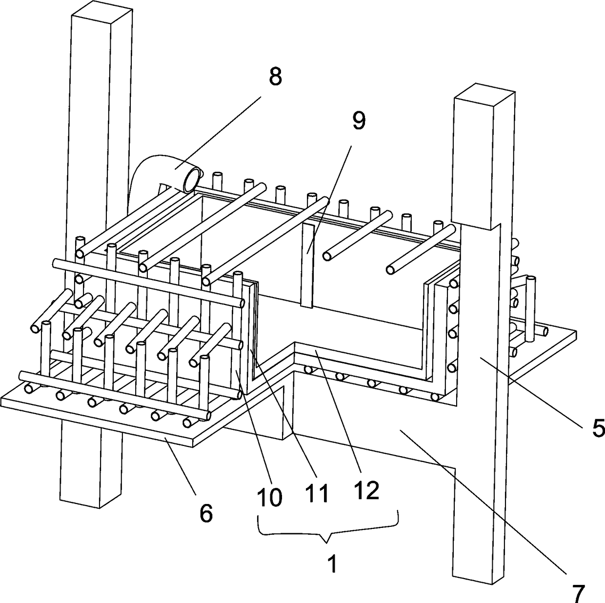
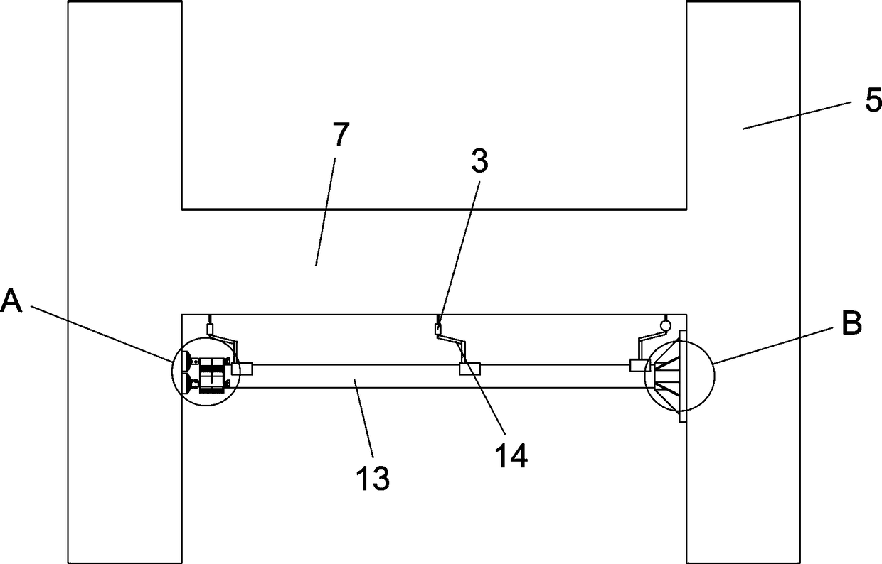
[0051] The invention discloses an on-site detection device suitable for the bearing capacity of reinforced concrete beams, which includes a beam 7 to be inspected, a floor 6 arranged on the upper end of the beam 7 to be inspected, and load-bearing columns 5 on both sides. The lower side of the beam 7 to be inspected is A displacement meter support 4 is arranged horizontally, and both sides of the displacement meter support 7 are detachably fixed between the two load-bearing columns 5, and a displacement meter is arranged between the inspected beam 7 and the displacement meter support 4. 3. The upper end of the inspected beam 7 is provided with a loading water tank 1 , and one side of the loaded water tank 1 is provided with a water delivery pipe 8 , and a plurality of strain gauges 2 are attached to the key stress points of the steel b...


PUM


Abstract

The invention relates to the technical field of field detection of the bearing capacity of reinforced concrete beams, in particular to a field detection device suitable for the bearing capacity of reinforced concrete beams and an arranging method. The field detection device comprises a detected beam, a floor slab arranged at the upper end of the detected beam and load-bearing columns arranged on the two sides of the detected beam; a displacement meter bracket is horizontally arranged on the lower side of the detected beam, and the two sides of the displacement meter brackets are detachably fixed between the two load-bearing columns; displacement meters are arranged between the detected beam and the displacement meter brackets; a loading water tank is arranged at the upper end of the detected beam, and a water delivering pipeline is arranged on one side of the loading tank; and a plurality of strain gauges are attached to a steel bar key stress point of the detected beam. The structureof the displacement meter bracket is simplified, the bracket is only composed of a longitudinal steel pipe and fixing devices at the two ends, and mounting is convenient and quick.

Description

technical field [0001] The invention relates to the technical field of on-site detection of the bearing capacity of reinforced concrete beams, in particular to an on-site detection device suitable for the bearing capacity of reinforced concrete beams and a setting method thereof. Background technique [0002] In building quality inspection and building structure renovation, it is often necessary to obtain the ultimate bearing capacity of a reinforced concrete beam. Stack loads above the beam body, paste strain gauges at the key stress points of the steel bars in the beam body, build displacement gauge supports under the beam body, arrange displacement gauges at the mid-span and beam ends, and stack loads on top to conduct bearing capacity testing tests . [0003] The traditional setting method of the displacement meter support is as follows: the longitudinal steel pipe parallel to the beam and the horizontal steel pipe perpendicular to the beam are built into a "ladder"-sha...

Claims


Application Information

Patent Timeline
Patent Type & Authority Applications(China)
IPC IPC(8): G01N3/08E04C3/20
CPCG01N3/08E04C3/20
Inventor 田钦杭成皓邹云朋刘鑫祺钟亮根陈为民黄发明
Owner NANCHANG UNIV
Learn More