Industrial machine vision system image processing method

A vision system and industrial machine technology, applied in image data processing, image enhancement, image analysis, etc., can solve the problems that the visual inspection system cannot cover 360 degrees, work efficiency is low, and defect detection cannot be realized.

Pending Publication Date: 2019-02-22
NANTONG SCI & TECH VOCATIONAL COLLEGE
View PDF11 Cites 19 Cited by
  • Summary
  • Abstract
  • Description
  • Claims
  • Application Information

AI Technical Summary

Problems solved by technology

[0004]The invention patent of CN104971973B "A Car Wheel Cover Hemming System and Its Using Method" mentions the application of the vision system, but it is limited to the positioning function of the vision system
However, its technical solution is limited to the pre-set trajectory optimization, which cannot solve the problem that the traditional visual inspection system based on a single camera cannot cover 360 degrees, and defect detection cannot be realized in some areas
[0006]The technical solution disclosed in CN201810494716's invention patent "A Machine Vision Inspection and Screening Device and Inspection System Based on Line Scan Camera" realizes multi-angle coverage inspection , but this technical solution needs to install a specific rotating mechanism on the production line to detect defects around the object, but it is inconvenient to use, and the work efficiency is low, and the defects on the upper surface of the object cannot be detected, so it cannot truly realize all-round defect detection
[0007] In addition, the application of machine vision technology in industrial systems in the prior art still has the following problems: With the development of science and technology, parts in the industrial field The structure is becoming more and more complex, and various defects in micro-pipes or small-sized characteristic inner holes are difficult to be observed due to the detection accuracy and detection orientation.
The application scenarios of this method are relatively single, and the use occasions of the measurement calculation method itself have not been more reasonably utilized

Method used


Image

  • Industrial machine vision system image processing method
  • Industrial machine vision system image processing method
  • Industrial machine vision system image processing method

Examples


Embodiment Construction

[0049] The embodiments of the present invention are described in detail below. Examples of the embodiments are shown in the accompanying drawings, wherein the same or similar reference numerals indicate the same or similar elements or elements with the same or similar functions. The following embodiments described with reference to the accompanying drawings are exemplary, and are only used to explain the present invention, and cannot be construed as limiting the present invention.

[0050] The technical scheme of the present invention will be further described in detail below in conjunction with the accompanying drawings:

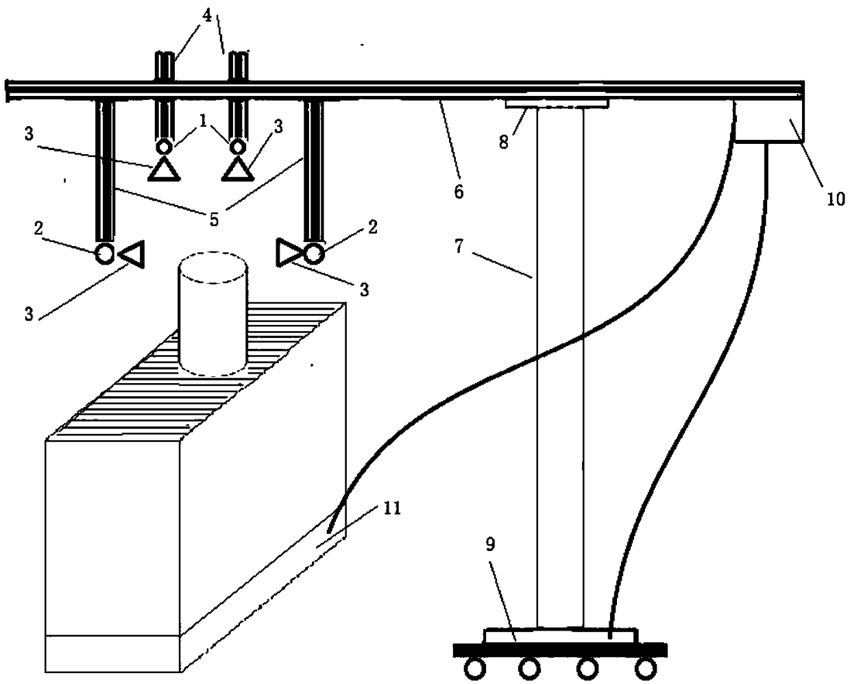
[0051] The image processing method of the industrial machine vision system disclosed in the present invention has a schematic diagram of the system hardware structure on which it depends figure 1 As shown, the industrial machine vision system based on the improved sensor detection device includes a sampling framing system, a displacement device, and a feedback l...


PUM


Abstract

The invention discloses an industrial machine vision system image processing method. The method is based on an industrial machine vision system hardware architecture which comprises a sampling and viewfinding system, a displacement device and a feedback linkage system which are set in data transmission and control transmission connection. According to the method, a high-precision measurement device based on light reflection is internally provided with a plurality of light sources, and the three-dimensional shape of a defective product is reconstructed by images in different illumination modes.The high-precision measurement device based on light reflection is embedded, and whether a micro pipeline or a small side characteristic inner hole has a product defect is determined according to collected high-precision image feedback. According to the invention, by a viewfinding component and a displacement device, the systems integrally move following the process sequence of an industrial processing production line to be detected, the processing precision of the processing line is monitored, the reverse early warning or correction of production line action is carried out, and the problemsgenerated in a production process are adjusted.

Description

Technical field [0001] The invention discloses an image processing method for an industrial machine vision system, and relates to the technical field of machine vision. Background technique [0002] Machine vision is a branch of artificial intelligence that is developing rapidly. Simply put, machine vision is to use machines instead of human eyes for measurement and judgment. The machine vision system converts the captured target into an image signal through a machine vision product (ie, image capture device, divided into CMOS and CCD), and transmits it to a dedicated image processing system to obtain the shape information of the captured target, according to the pixel distribution Information such as brightness and color are transformed into digital signals; the image system performs various operations on these signals to extract the characteristics of the target, and then controls the actions of the equipment on the spot according to the results of the discrimination. In mass...

Claims


Application Information

Patent Timeline
Patent Type & Authority Applications(China)
IPC IPC(8): G05B19/05G06K9/00G06T7/00G06T7/13G06T7/136
CPCG05B19/054G06T7/001G06T7/13G06T7/136G05B2219/1103G06T2207/10004G06T2207/30108G06V20/10
Inventor 陈林琳黄菊于翔杨健兵
Owner NANTONG SCI & TECH VOCATIONAL COLLEGE
Why Eureka
Try Eureka