
Liquid cooling iron core structure of electromagnetic induction element

A technology of electromagnetic induction and iron core structure, which is applied in electrical components, transformer/inductor cooling, transformer/inductor magnetic core, etc., and can solve problems such as complex transformer structure

Pending Publication Date: 2019-02-22
HEFEI ECRIEE TAMURA ELECTRIC
View PDF1 Cites 1 Cited by
  • Summary
  • Abstract
  • Description
  • Claims
  • Application Information

AI Technical Summary

Problems solved by technology

However, the structure of the transformer is more complex

Method used


Image

  • Liquid cooling iron core structure of electromagnetic induction element
  • Liquid cooling iron core structure of electromagnetic induction element

Examples


Embodiment Construction

[0015] The following description is used to disclose the present invention so that those skilled in the art can implement the present invention. The preferred embodiments in the following description are only examples, and those skilled in the art can think of other obvious variations.

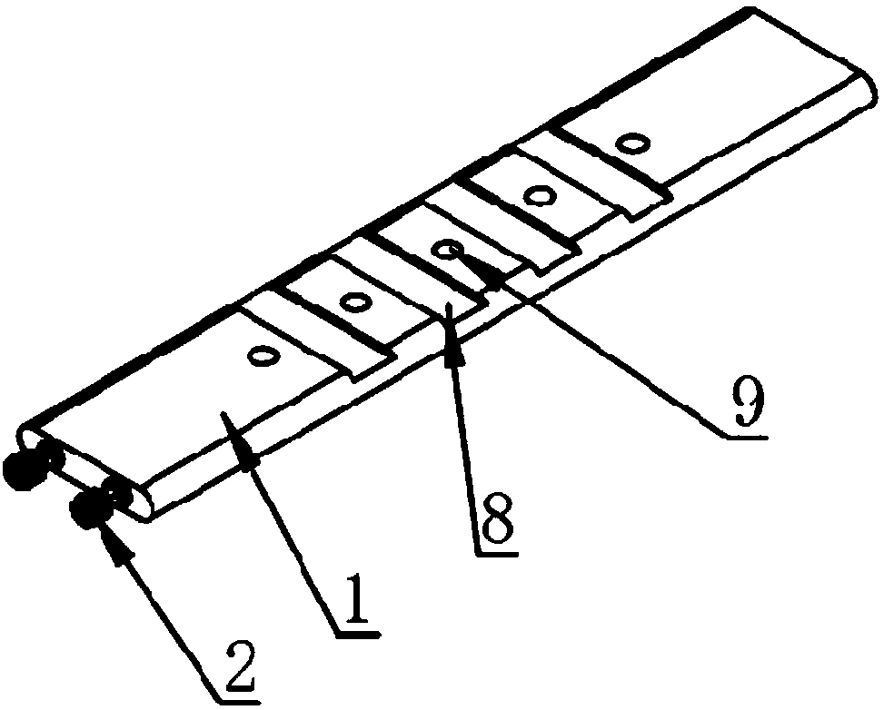
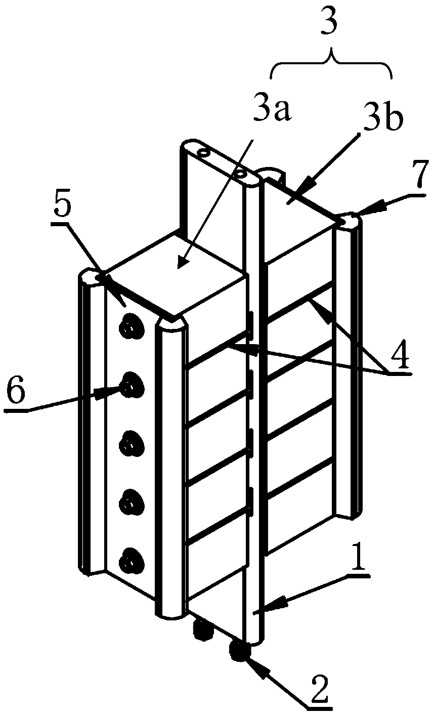
[0016] Such as figure 1 with figure 2 As shown, the liquid-cooled iron core structure (iron core structure for short) of the electromagnetic induction element provided by the present invention includes an iron core 3, a heat dissipation plate 1 and a fixing plate 5. The iron core 3 is a split structure, which is composed of a first iron core post 3a on the left and a second iron core post 3b on the right. The magnetic circuit directions of the first iron core leg 3a and the second iron core leg 3b are figure 2 The up and down direction. The projections of the first iron core leg 3a and the second iron core leg 3b on the cross section perpendicular to the magnetic circuit are rectangular. A ...


PUM


Abstract

The invention provides a liquid cooling iron core structure of an electromagnetic induction element. The structure comprises an iron core, heat dissipation plates and fixing plates. The iron core is composed of multiple iron core posts which are arranged side by side and split. The heat dissipation plates are clamped between the adjacent iron core posts, and channels allowing cooling liquid to flow are formed in the heat dissipation plates. The fixing plates are located on the two sides of the iron core and clamped and fixed to the two sides of the iron core. The iron core structure has the advantages of being small in size, easy to machine and manufacture and good in heat dissipation effect, and has wide application prospects.

Description

Technical field [0001] The invention relates to the technical field of power electronics, and in particular to an iron core structure of an electromagnetic induction element. Background technique [0002] Both reactors and transformers are electromagnetic induction elements wound with insulated wires. When reactors and transformers work, their coils will generate a steady stream of heat. If the heat is not consumed in time, it will affect the performance and life of the entire electromagnetic induction element, and even cause safety hazards. [0003] In the prior art, cooling methods for electromagnetic induction elements mainly include air cooling, air cooling, and liquid cooling. Because of its high cooling efficiency, liquid cooling has become one of the key directions for the development of electromagnetic induction element cooling technology. Chinese patent CN204315353 U discloses a liquid-cooled transformer, which includes an iron core, an input coil and an output coil woun...

Claims


Application Information

Patent Timeline
Patent Type & Authority Applications(China)
IPC IPC(8): H01F27/08H01F27/10H01F27/22H01F27/24H01F27/26H01F27/34
CPCH01F27/085H01F27/10H01F27/22H01F27/24H01F27/263H01F27/34
Inventor 刁连杰
Owner HEFEI ECRIEE TAMURA ELECTRIC
Learn More