Supercharge Your Innovation With Domain-Expert AI Agents!

Power metering cabinet dust removal device

A technology for power metering cabinets and dust removal devices, which is applied to substation/distribution device shells, smoke and dust removal, chemical instruments and methods, etc., can solve the problems of increasing hidden dangers of equipment failure, re-accumulation of dust, and reducing the insulation performance of insulators, etc., to achieve Fast and efficient dust removal, enhanced dust removal efficiency, and simple structure

Inactive Publication Date: 2019-02-22
TIANJIN LNER ELECTRIC
View PDF5 Cites 0 Cited by
  • Summary
  • Abstract
  • Description
  • Claims
  • Application Information

AI Technical Summary

Problems solved by technology

[0002] The factory computer room is generally equipped with a lot of electrical equipment and metering cabinets. The environment of this kind of computer room usually needs to be controlled at an appropriate temperature and humidity to ensure the normal operation of the system. However, due to the dust and dust in the industrial site environment, dust A large amount of accumulation will reduce the insulation performance of insulators, shorten the service life of electronic components, and increase the failure rate of electrical equipment, thus directly affecting the safe and stable operation of industrial process control systems
[0003] At present, the dust removal method mainly uses a hand-held soot blower for blowing, which is not only time-consuming and laborious, but also the dust cannot be collected and discharged into the cabinet, which will still cause dust to accumulate again, which cannot achieve the ideal dust removal effect and increases the hidden danger of equipment failure

Method used


Image

  • Power metering cabinet dust removal device
  • Power metering cabinet dust removal device

Examples


Embodiment Construction

[0014] The following will clearly and completely describe the technical solutions in the embodiments of the present invention with reference to the accompanying drawings in the embodiments of the present invention. Obviously, the described embodiments are only some, not all, embodiments of the present invention. Based on the embodiments of the present invention, all other embodiments obtained by persons of ordinary skill in the art without making creative efforts belong to the protection scope of the present invention.

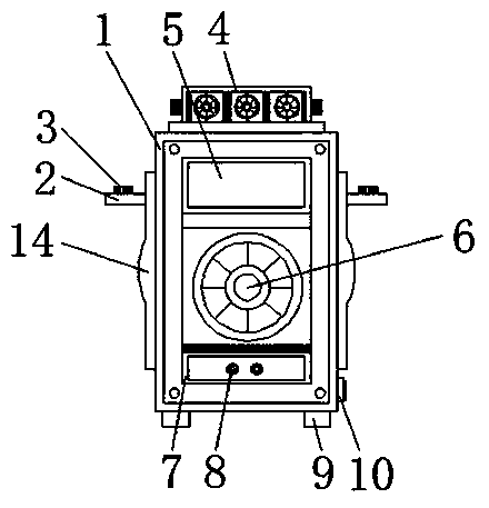
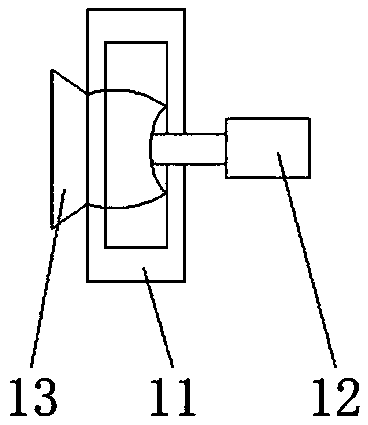
[0015] see figure 1 and figure 2 , the present invention provides a technical solution: a dust removal device for a power metering cabinet, including a metering cabinet body 1, a fixing plate 2, a nut 3, a vacuum cleaner 4, a viewing window 5, a dust removal fan 6, a dust collection tank 7, and a dust concentration sensor 8. Support plate 9, dust outlet 10, fan fixing table 11, drive motor 12, deflector 13 and protective cover 14, the left side of the meteri...


PUM


Abstract

The invention discloses a power metering cabinet dust removal device. The power metering cabinet dust removal device comprises a metering cabinet body, a fixing plate, a nut, a vacuum cleaner, a viewing window, a dust removing fan, a dust collecting groove, a dust concentration sensor, a support plate, a dust exhaust port, a fan fixing platform, a driving motor, a deflector and a protective cover,wherein the metering cabinet body is equipped with the dust removing fan therein; the dust collecting groove is arranged on the lower side of the dust removing fan; the dust concentration sensor is arranged on the lower side of the viewing window; the support plate is fixed to the bottom of the metering cabinet body; the dust exhaust port is disposed on the lower side of the right end of the metering cabinet body; the dust removing fan is fixed to the fan fixing platform; and the driving motor is disposed on the right side of the fan fixing platform. The power metering cabinet dust removal device is simple in structure and convenient to control, removes dust by wind in a fast and high-efficient way, can remove the dust stored in the metering cabinet at a time, and is provided with a dustcollecting device and the dust exhaust port, can collect dust and discharge the dust out of the cabinet, and greatly enhances the dust removal efficiency.

Description

technical field [0001] The invention relates to the technical field of dust removal for power metering cabinets, in particular to a dust removal device for power metering cabinets. Background technique [0002] The factory computer room is generally equipped with a lot of electrical equipment and metering cabinets. The environment of this kind of computer room usually needs to be controlled at an appropriate temperature and humidity to ensure the normal operation of the system. However, due to the dust and dust in the industrial site environment, dust A large amount of accumulation will reduce the insulation performance of insulators, shorten the service life of electronic components, and increase the failure rate of electrical equipment, which directly affects the safe and stable operation of industrial process control systems. [0003] At present, the dust removal method mainly uses a hand-held soot blower for blowing, which is not only time-consuming and laborious, but al...

Claims


Application Information

Patent Timeline
Patent Type & Authority Applications(China)
IPC IPC(8): H02B1/30H02B1/28B08B5/02B08B15/00
Inventor 王茂泉
Owner TIANJIN LNER ELECTRIC
Features
  • R&D
  • Intellectual Property
  • Life Sciences
  • Materials
  • Tech Scout
  • Unparalleled Data Quality
  • Higher Quality Content
  • 60% Fewer Hallucinations
Learn More