
LED illumination control method and device

A light-emitting diode and light-emitting control technology, which is applied to electroluminescent light sources, lighting devices, light sources, etc., can solve the problems that light-emitting diodes cannot achieve brightness, speed, and dynamic adjustment.

Active Publication Date: 2019-02-22
SHENZHEN H&T INTELLIGENT CONTROL
View PDF7 Cites 6 Cited by
  • Summary
  • Abstract
  • Description
  • Claims
  • Application Information

AI Technical Summary

Problems solved by technology

[0004] In view of the above-mentioned defects of the prior art, the object of the present invention is to provide a method and device for controlling the light emission of light-emitting diodes, which can solve the problem that the brightness and speed of light-emitting diodes cannot be dynamically adjusted at the same time

Method used


Image

  • LED illumination control method and device
  • LED illumination control method and device
  • LED illumination control method and device

Examples


Embodiment 1

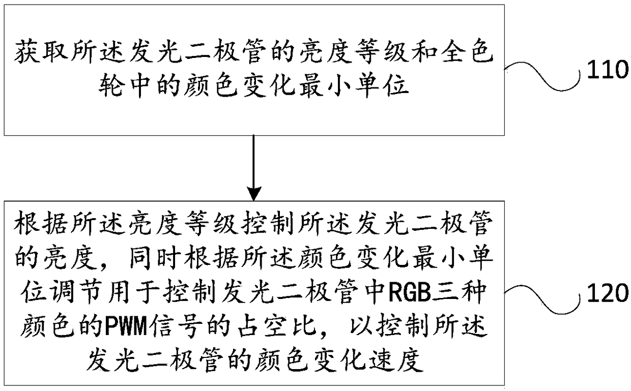
[0063] figure 1 It is a schematic flow chart of a light emitting diode control method provided in the embodiment of this application, please refer to figure 1 , the method includes but is not limited to the following steps:

[0064] Step 110: Obtain the brightness level of the LED and the minimum unit of color change in the full color wheel.

[0065] In the embodiment of the present application, the "light-emitting diode brightness level" (RGB brightness level) is an optional range of the overall brightness of the light-emitting diode, which can uniformly adjust the brightness of the red, green and blue color channels of the light-emitting diode . The "minimum unit of color change in the full color wheel" is the color change value generated in the full color wheel when one of the three colors of the LED changes.

[0066] In the embodiment of the present application, the specific implementation of "obtaining the brightness level of the light-emitting diode" can be: by settin...

Embodiment 2

[0112] Figure 4 It is a schematic diagram of a light-emitting diode lighting control device provided in the embodiment of this application, please refer to Figure 4 , the LED lighting control device 200 includes but not limited to: an acquisition module 210 , a control module 220 and a determination module 230 .

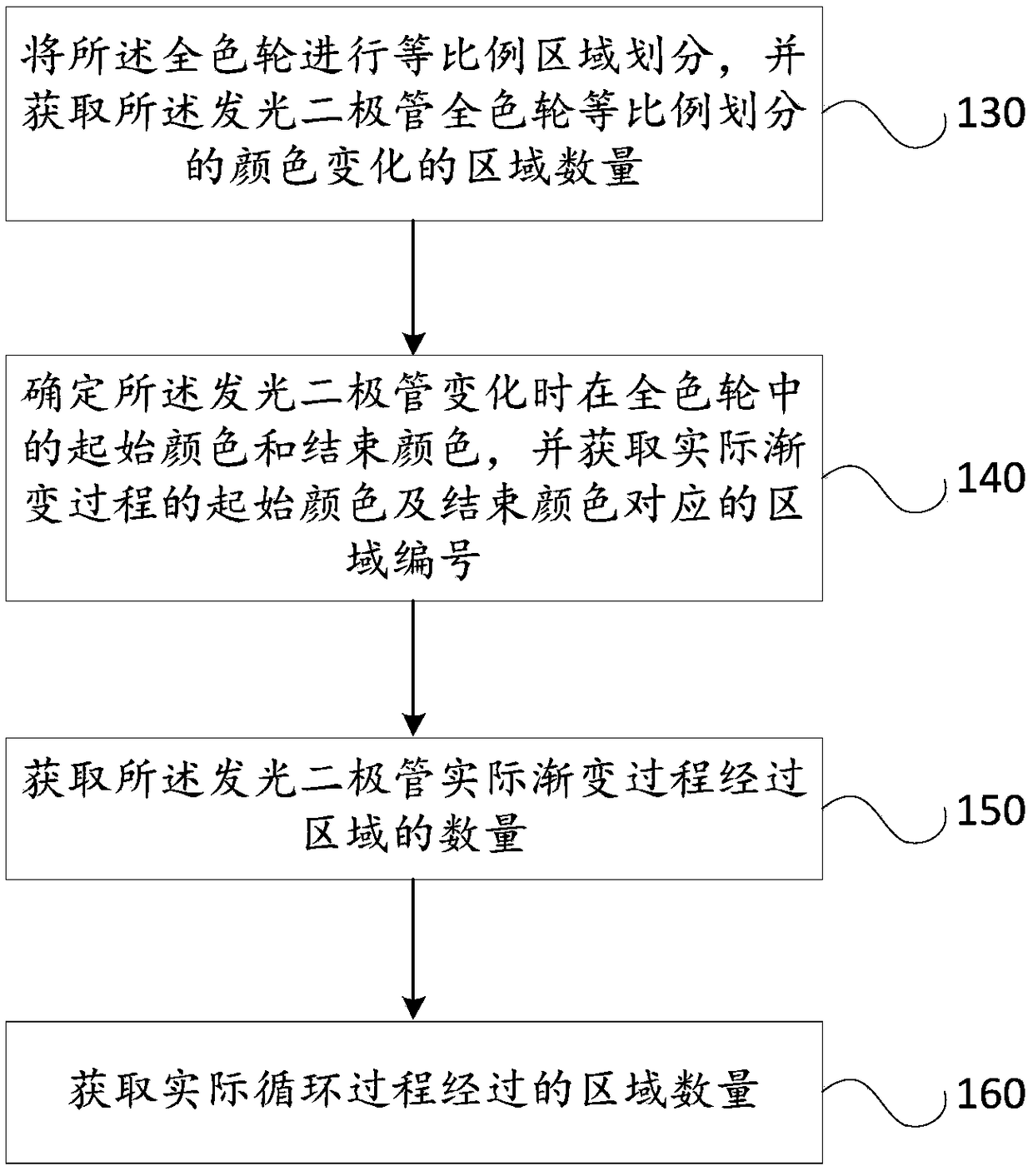
[0113] Wherein, the acquiring module 210 is used to acquire the brightness level of the light emitting diode and the smallest unit of color change in the full color wheel; the acquiring module 210 is also used to acquire the color change of the equal proportion division of the full color wheel of the light emitting diode The number of areas; the acquisition module 210 is also used to acquire the number of areas passed by the actual gradation process of the light emitting diode; the acquisition module 210 is also used to acquire the area number corresponding to the start color and the end color of the actual gradation process; and The obtaining module 210 is also use...

Embodiment 3

[0141] Figure 5 It is a structural schematic diagram of a colored light provided in the embodiment of the present application. The colored light 300 can be any RGB colored light that can realize various colors and accept PWM signals, for example, LED light strips, LED rotating colored lights, etc., can Execute the method for controlling light emission of a light emitting diode provided in the embodiment of the present application.

[0142] Specifically, see Figure 5 , the colorful lamp 300 includes: a light emitting diode 310; and a microcontroller 320 capable of controlling the light emitting of the light emitting diode 310, Figure 5 Take the electrical connection between the microcontroller 320 and the LED 310 as an example.

[0143] There are one or more light emitting diodes 310, and the light emitting diodes 310 can receive the pulse signals of the three color channels of R, G, and B, so as to emit mixed light of R, G, and B with different brightness at a set change ...


PUM


Abstract

The invention discloses an LED illumination control method and device applied to a lantern including an LED and a microcontroller. The method in the embodiment of the present application comprises obtaining the brightness level of the LED and the color change minimum unit in a full color wheel; controlling the brightness of the LED according to the brightness level; and adjusting the duty ratio ofa PWM signal for controlling three colors RGB in the LED according to the color change minimum unit to control the color change speed of the LED and achieve a dimming and speed regulation purpose.

Description

technical field [0001] The invention relates to the field of lighting control, in particular to a method and device for controlling light emission of a light emitting diode. Background technique [0002] The application of lighting is very extensive. In homes, shopping malls, stages, and even many public places, there are all kinds of lighting, and the forms of display are also diversified. In most cases, the colorful lights used as ambient lights also play an indispensable role, and most of the colored lights are composed of RGB LEDs, which originate from the principle of three primary color mixing of visible light in nature, and can be controlled by PWM through MCU. To achieve different ratios of RGB mixed with each other to get the required color. [0003] In the process of realizing the present invention, the inventors found that there are at least the following problems in the above related technologies: at present, most RGB LED products can display multiple static col...

Claims


Application Information

Patent Timeline
Patent Type & Authority Applications(China)
IPC IPC(8): H05B33/08H05B44/00
CPCH05B45/14H05B45/24
Inventor 麦嘉逊朱志峰刘定源
Owner SHENZHEN H&T INTELLIGENT CONTROL
Learn More