Suction nozzle for vacuum cleaner and method for operating suction nozzle

A technology for suction nozzles and vacuum cleaners, which is applied in the direction of vacuum cleaners, suction nozzles, applications, etc., and can solve problems such as increased movement resistance

Inactive Publication Date: 2019-02-26
VORWERK & CO INTERHOLDING GMBH
View PDF0 Cites 2 Cited by
  • Summary
  • Abstract
  • Description
  • Claims
  • Application Information

AI Technical Summary

Problems solved by technology

[0006] However, a high degree of sealing to the floor to be cleaned has the disadvantage that the movement resistance of the suction nozzle to the user operating the suction nozzle increases

Method used


Image

  • Suction nozzle for vacuum cleaner and method for operating suction nozzle

Examples


Embodiment Construction

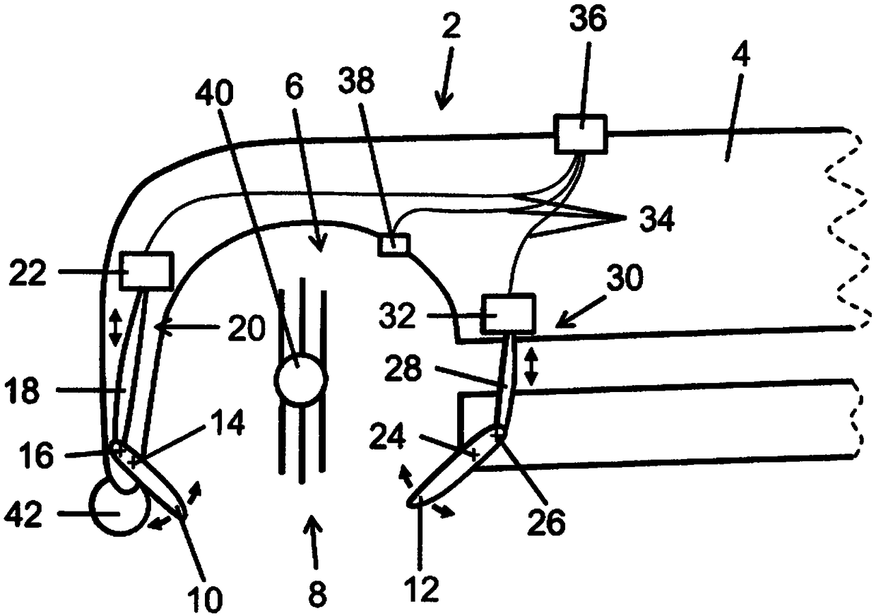
[0034] exist figure 1 A schematic diagram of an embodiment of the front part of the suction nozzle 2 according to the invention is shown in side view. The suction nozzle 2 has a housing 4 , a suction chamber 6 arranged in the housing 4 and a suction opening 8 formed in the housing 4 . The suction chamber 6 or the suction opening 8 is at least partially sealed off from the front by the first delimiter 10 and from the rear by the second delimiter 12 against the bottom surface to be cleaned.

[0035]The first limiting member 10 and the second limiting member 12 are here designed in the form of flexible slides. However, it is also possible for the invention to design the two delimiting elements 10 and 12 as sealing lips.

[0036] The suction chamber 6 or the suction opening 8 is also sealed laterally from the floor to be cleaned by delimiting elements not shown. This delimiter can be designed, for example, as a sealing lip, a sliding strip or a housing part.

[0037] The first...


PUM


Abstract

The invention relates to a suction nozzle for a vacuum cleaner, comprising a housing (4), a suction chamber (6) arranged in the housing (4), a suction mouth (8) formed in the housing (4), at least onefirst limiting element (10), and at least one second limiting element (12), wherein the first limiting element (10) and the second limiting element (12) limit the suction mouth (8) for a floor to becleaned. The technical task of providing a suction nozzle which has good dust absorption values and low resistance to movement is achieved according to the invention in that at least one control means(20, 30) controls the first limiting element (10) and/or the second limiting element (12) to move during a suction process. The invention also relates to a method for operating a suction nozzle.

Description

technical field [0001] The invention relates to a suction nozzle for a vacuum cleaner, which has a housing, a suction chamber arranged in the housing, a suction opening formed in the housing, at least one first limiter and at least one second limiter. parts, wherein the first restricting part and the second restricting part define the suction port on the ground to be cleaned. Furthermore, the invention relates to a method for operating a suction nozzle. Background technique [0002] The suction nozzle, as an accessory, referred to as a hard floor nozzle or a motorized brush according to the intended use, is typically fluid-tightly connected to the floor vacuum cleaner via a flexible suction and / or operating pipe. In so-called hand-held vacuum cleaners, the suction nozzle can also be connected directly to the main body of the vacuum cleaner in a fluid-tight manner. In robot vacuum cleaners, the base body of the vacuum cleaner is constructed in one piece with the suction noz...

Claims


Application Information

Patent Timeline
Patent Type & Authority Applications(China)
IPC IPC(8): A47L9/04
CPCA47L9/04A47L9/064A47L9/066A47L9/0405A47L9/0466A47L9/0483A47L9/0488
Inventor 马库斯·科内利森
Owner VORWERK & CO INTERHOLDING GMBH
Why Eureka
Try Eureka