Automobile part grinding tool

A technology of auto parts and tooling, which is applied in the direction of grinding/polishing safety devices, grinding machines, manufacturing tools, etc. It can solve the problems of the environment affecting the processing of auto parts, inconvenience for users, and easy to scratch auto parts, etc., to achieve Improve the dust collection effect and facilitate the grinding effect

Inactive Publication Date: 2019-02-26
重庆精高金属结构制造有限公司
5 Cites 0 Cited by

AI-Extracted Technical Summary

Problems solved by technology

[0002] During the processing of auto parts, grinding tooling is needed to remove the burrs on the surface of auto parts. The grinding tooling needs fixtures to fix the auto parts when polishing the auto parts. The existing ...

Abstract

The invention discloses an automobile part grinding tool which comprises a base, a transparent dustproof cover, an installing box, a base plate, a rubber suction cup and a sleeve. A fixing plate is arranged at the upper end of a first electric stretchable rod, a first motor is arranged on the fixing plate, the first motor is connected with one end of a grinding shaft through a coupler, a grindingtool is connected with a grinding shaft through a fixing bolt, the inner wall of the transparent dustproof cover is connected with the connecting sleeve through a connecting piece, the connecting sleeve sleeves the end of a dust removal pipe, a dust removal head is arranged at one end of the dust removal pipe, the other end of the dust removal pipe is connected with a dust remover, a fixing base is welded to the bottom of the base, a second motor is welded to the upper end of the fixing base, the second motor is connected with a rotating shaft through a coupler, a rotating disc is welded to the upper end of the rotating shaft, a fixing block is arranged at the upper side of the rotating disc, and the fixing block is connected with a clamp through a second motor stretchable rod. The grinding tool is composed of a grinding head and the sleeve. The sleeve is welded to one side of the grinding head, and the grinding tool can be disassembled and replaced as needed.

Application Domain

Technology Topic

Image

  • Automobile part grinding tool
  • Automobile part grinding tool
  • Automobile part grinding tool

Examples

  • Experimental program(1)

Example Embodiment

[0024] Examples:
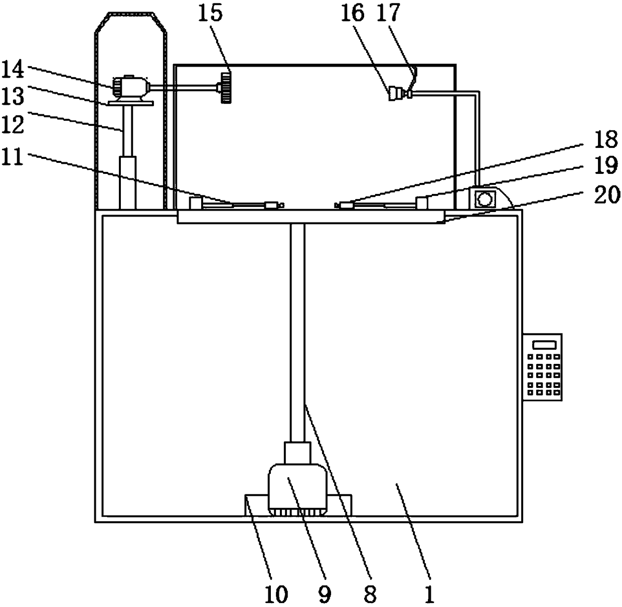
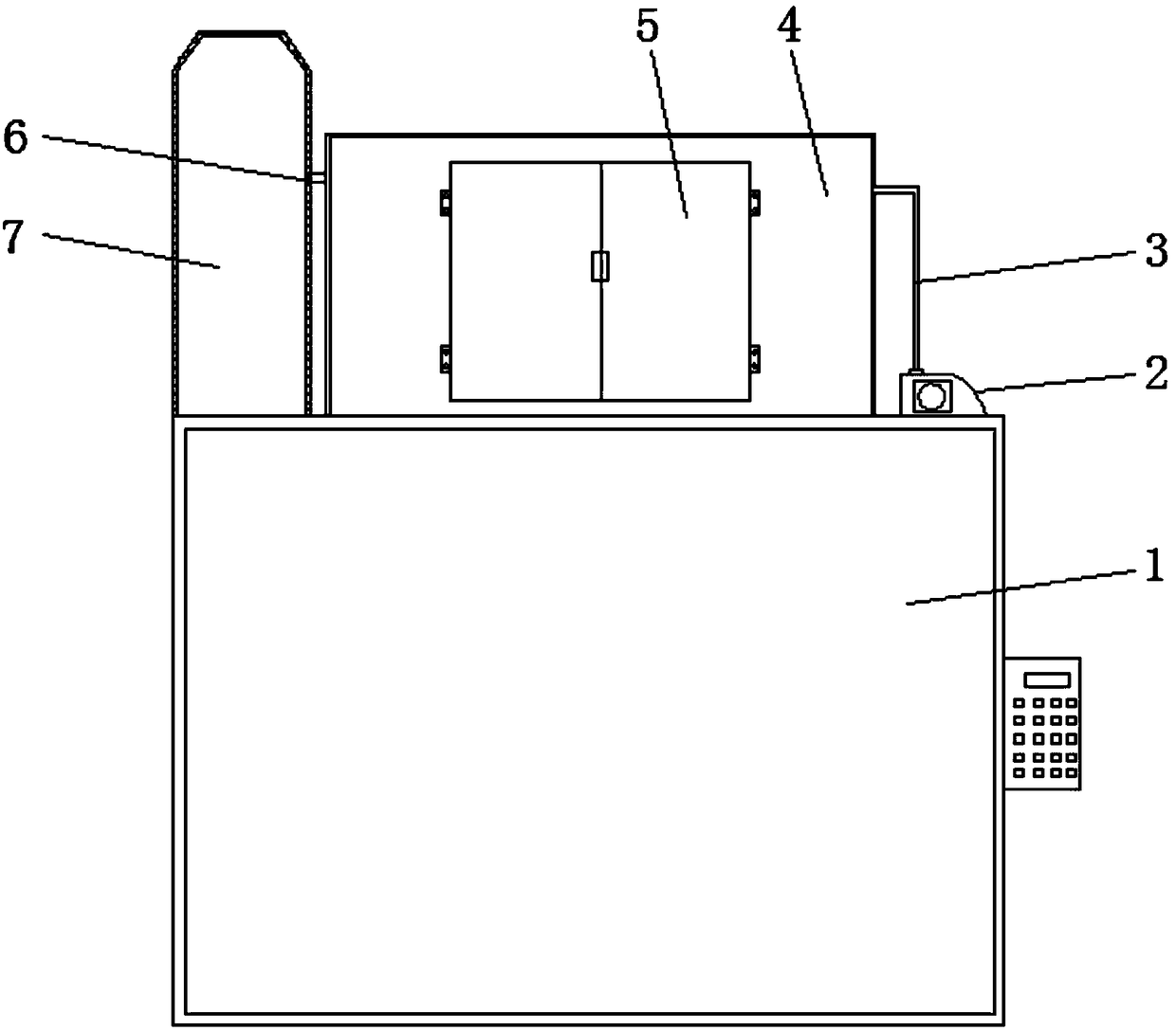
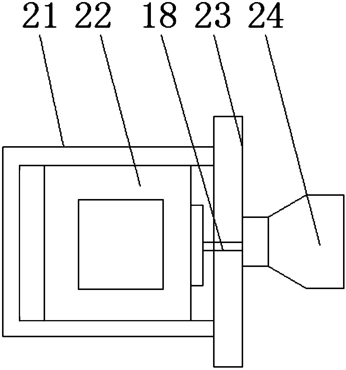
[0025] Such as Figure 1 to Figure 4 As shown, a polishing tool for auto parts includes a base 1, a transparent dust cover 4, a mounting box 21, a bottom plate 23, a rubber suction cup 24, and a sleeve 25. A PLC controller is provided on one side of the base 1 and the upper side of the base 1 A housing 7, a transparent dust cover 4, a vacuum cleaner 2 and a first electric telescopic rod 12 are provided. The first electric telescopic rod 12 is located inside the housing 7, and the upper end of the first electric telescopic rod 12 is provided with a fixed plate 13 and the fixed plate 13 A first motor 14 is provided on the upper part. The first motor 14 is connected to one end of the grinding shaft 6 through a coupling. The other end of the grinding shaft 6 passes through the elongated through hole on the housing 7 and is connected to the grinding tool 15. The fixing bolt is connected to the grinding shaft 6, and the fixing bolt penetrates the threaded hole on the grinding tool 15 and the grinding shaft 6. The lower end of the fixing bolt is threaded with a nut. The grinding tool 15 is located inside the transparent dust cover 4, and the grinding shaft 6 and the transparent guard The elongated through holes on the dust cover 4 are movably connected. The inner wall of the transparent dust cover 4 is connected to the connecting sleeve through the connecting piece 17. The connecting sleeve is sleeved at the end of the dust suction pipe 3, and the dust suction head 16 is installed at one end of the suction pipe 3 , The other end of the vacuum tube 3 is connected to the vacuum cleaner 2, the front surface of the transparent dust cover 4 is hinged with a door 5 through a hinge, and the doors 5 are connected by a buckle. The bottom of the base 1 is welded with a fixing seat 10 and a fixing seat 10 The upper end of the second motor 9 is welded, and the second motor 9 is connected to the rotating shaft 8 through a coupling. The upper end of the rotating shaft 8 is welded with a turntable 20. The turntable 20 is located in the circular opening on the base 1. The upper side of the turntable 20 is provided with a fixed Block 19, the fixed block 19 is connected by the second electric telescopic rod 11 and the clamp 18, when used, the first electric telescopic rod 12, the second electric telescopic rod 11, the first motor 14, the second motor 9, the micro air pump 22 and The vacuum cleaner 2 is connected to the power supply through a PLC controller. The PLC controller is an S430A PLC controller. The first motor 14 and the second motor 9 are both YL-type motors. The auto parts to be processed are placed on the turntable 20, and the two second The electric telescopic rod 11 drives the clamp 18 to clamp the auto parts, and then adjusts the height of the first motor 14 through the first electric telescopic rod 12 according to the grinding requirements, so as to realize the adjustment of the height of the grinding tool 15. The first motor 14 is polished The shaft 6 drives the grinding tool 15 to rotate, so as to achieve a good grinding of auto parts. The second motor 9 drives the turntable 20 to rotate through the rotating shaft 8. The turntable 20 can well adjust the angle of the auto parts, thus achieving Grinding at different angles, the dust generated by the grinding is sucked into the vacuum cleaner 2 through the vacuum head 16 and the vacuum pipe 3.
[0026] Reference image 3 As shown, the clamp 18 includes a mounting box 21, a micro air pump 22 is provided inside the mounting box 21, a bottom plate 23 is provided on one side of the mounting box 21, and a rubber suction cup 24 is provided on one side of the bottom plate 23. The rubber suction cup 24 is connected to the micro air pump 22 through a pipe. .
[0027] Reference Figure 4 As shown, the grinding tool 15 is composed of a grinding head 26 and a sleeve 25, and the sleeve 25 is welded to one side of the grinding head 26.
[0028] Reference figure 1 As shown, the connecting piece 17 is a universal elbow, and both ends of the connecting piece 17 are welded to the transparent dust cover 4 and the connecting sleeve.
[0029] Reference figure 1 As shown, the upper end surface of the turntable 20 is flush with the upper end surface of the base 1, and the diameter of the turntable 20 is smaller than the circular opening on the base 1 by 2 cm.
[0030] The working principle of the present invention is: when in use, the first electric telescopic rod 12, the second electric telescopic rod 11, the first motor 14, the second motor 9, the micro air pump 22 and the vacuum cleaner 2 are connected to the power source through the PLC controller. The controller is a S430APLC controller, the first motor 14 and the second motor 9 are both YL type motors, the auto parts to be processed are placed on the turntable 20, and the two second electric telescopic rods 11 drive the fixture 18 to the auto parts Clamping, and then adjust the height of the first motor 14 through the first electric telescopic rod 12 according to the grinding requirements, so as to realize the adjustment of the height of the grinding tool 15. The first motor 14 drives the grinding tool 15 to rotate through the grinding shaft 6, which is very good To realize the polishing of auto parts, the second motor 9 drives the turntable 20 to rotate through the rotating shaft 8. The turntable 20 can well adjust the angle of the auto parts, so as to realize the polishing of different angles and the dust generated by the polishing. The suction head 16 and the suction pipe 3 are sucked into the vacuum cleaner 2.

PUM

no PUM

Description & Claims & Application Information

We can also present the details of the Description, Claims and Application information to help users get a comprehensive understanding of the technical details of the patent, such as background art, summary of invention, brief description of drawings, description of embodiments, and other original content. On the other hand, users can also determine the specific scope of protection of the technology through the list of claims; as well as understand the changes in the life cycle of the technology with the presentation of the patent timeline. Login to view more.

Similar technology patents

Ball mill cooling method that can dedust the crushing workplace

ActiveCN103657829BImprove vacuuming effectShorten cooling timeGrain treatmentsBall millEngineering
Owner:ANHUI LIUGUO CHEM CO LTD

Brush head module for cleaning machine and cleaning machine

ActiveCN114652195AIncrease flow speedImprove vacuuming effectSuction filtersCarpet cleanersPhysicsMechanical engineering
Owner:NINGBO FOTILE KITCHEN WARE CO LTD

Glass kiln furnace production system

ActiveCN108623138AImprove vacuuming effectReduce pollutionGlass productionTuyereKiln
Owner:江苏慕宁建设工程有限公司

Rotary vane type vacuum pump eliminating harmful space

PendingCN112555151AReduce harmful spaceImprove vacuuming effectRotary piston pumpsRotary piston liquid enginesIndustrial engineeringControl theory
Owner:爱德华真空设备股份有限公司

Novel dedusting cabinet

Owner:NANAN HANGFENG ENERGY SAVING TECH

Classification and recommendation of technical efficacy words

  • Improve vacuuming effect
  • Easy to polish

Automatic packaging production line for industrial explosive

ActiveCN101393002AMeet the function of interchange productionImprove vacuuming effectAmmunition storageClip deviceManufacturing line
Owner:WUHAN RENTIAN PACKAGING TECH

Preparation method of superabsorbent short-fluff chenille printed floor mat

InactiveCN108086009AAchieve thick effectImprove vacuuming effectConstructions elementsDyeing processDigital printingAbsorption capacity
Owner:JINHUA JIELING HOUSE WARES CO LTD

Multifunctional wireless communication inspection robot

InactiveCN110328649AImprove vacuuming effectEasy loading and unloadingManipulatorEngineeringHigh intensity
Owner:PINGAN KAICHENG INTELLIGENT SAFETY EQUIP

Spinning machine provided with dust collection device

InactiveCN108505164AVacuum distance changeImprove vacuuming effectTextiles and paperYarnEngineering
Owner:YICHANG DIYUAN MEDICAL MATERIAL CO LTD
Why Eureka
Try Eureka