Supercharge Your Innovation With Domain-Expert AI Agents!

Back plate feeding manipulator fixture

A fixture device and manipulator technology, which is applied to conveyors, conveyor objects, transportation and packaging, etc., can solve the problems that four corner codes cannot be placed in the feeding position, inconvenient for processing and management, and inconvenient for reclaiming materials. Facilitate processing management, meet on-site process requirements, and reduce manpower

Pending Publication Date: 2019-02-26
SHANGHAI HUATAI INFORMATION TECH
View PDF0 Cites 5 Cited by
  • Summary
  • Abstract
  • Description
  • Claims
  • Application Information

AI Technical Summary

Problems solved by technology

When feeding, in order to protect the product and facilitate stacking, there will be four corner codes under the four corners of the product. When picking up the material, the four corner codes need to be taken out together, but the four corner codes cannot be placed on the loading material. Location
In the past, the above-mentioned operations were performed manually, resulting in higher costs, lower efficiency, inconvenient processing management, and inconvenient retrieving of materials, etc., and a little carelessness would damage the product

Method used


Image

  • Back plate feeding manipulator fixture
  • Back plate feeding manipulator fixture
  • Back plate feeding manipulator fixture

Examples


Embodiment Construction

[0035] Below, the product 11 is taken as an example of a TV backplane, and the present invention is further described in conjunction with the accompanying drawings and specific embodiments.

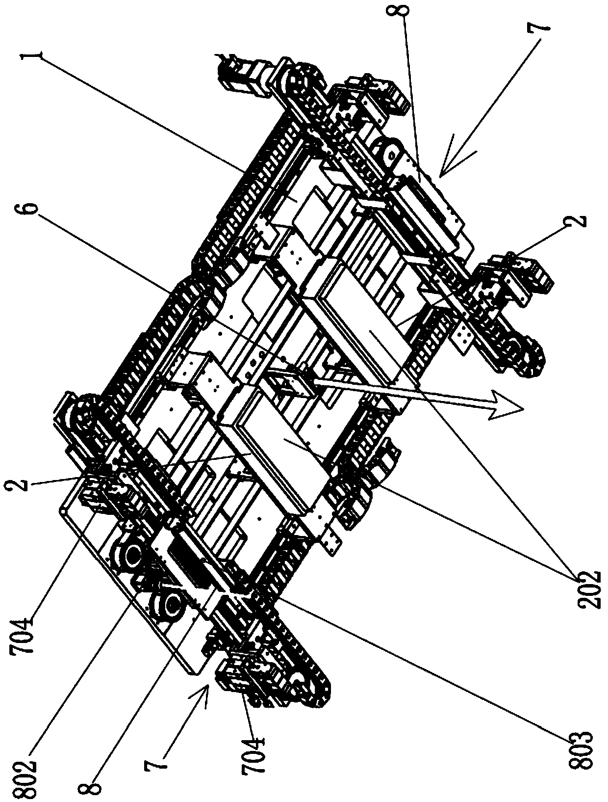
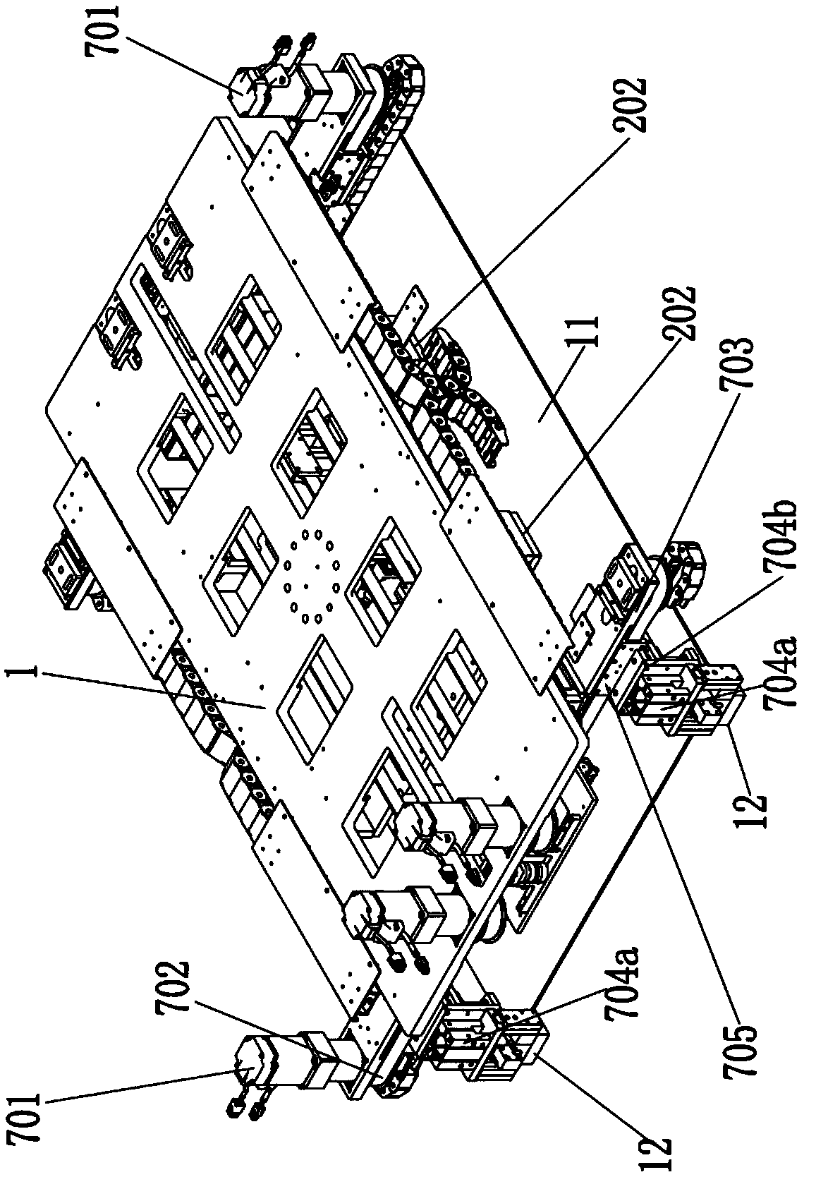
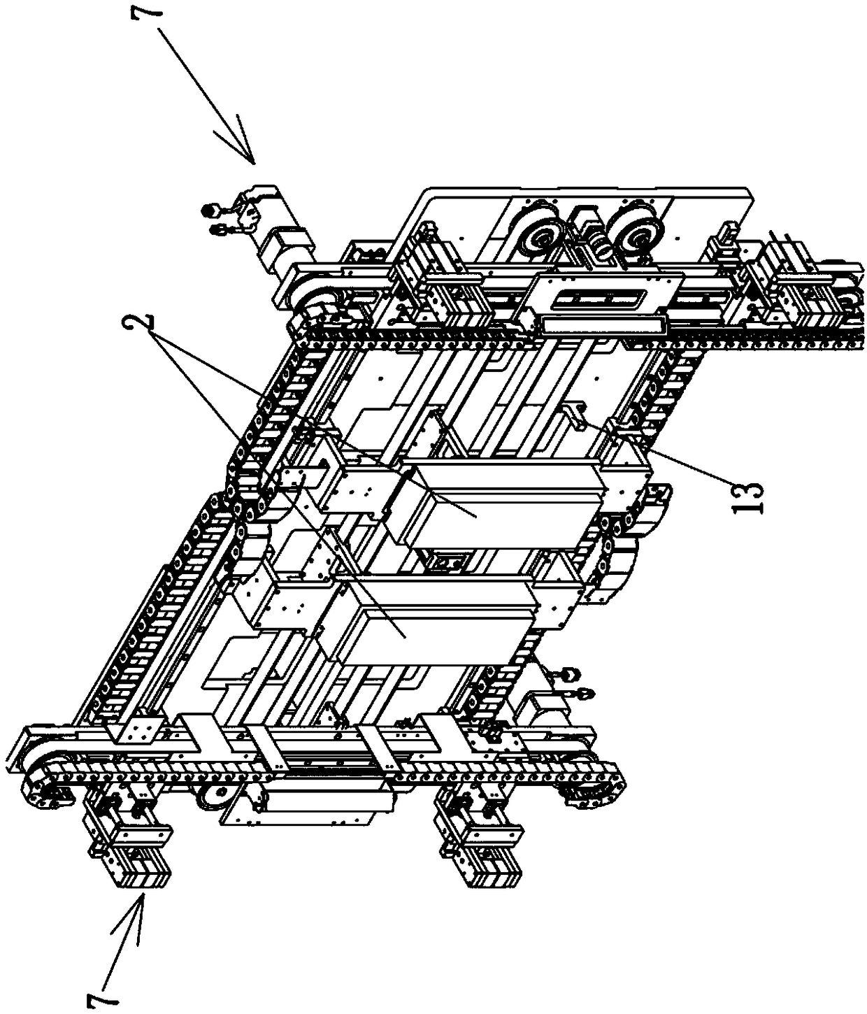
[0036] to combine figure 1 , 2 , 3, and 10, the fixture device of the backplane feeding manipulator includes the following parts:

[0037] The fixture main seat 1 connected with the execution end of the manipulator;

[0038] A pair of sucker group mechanisms 2 relatively slidably installed on the fixture main base 1 and slide horizontally along the X direction, the sucker group mechanisms 2 are used to absorb the product 11;

[0039] A suction cup group distance adjustment mechanism installed on the clamp main base 1 for driving the two suction cup group mechanisms 2 to slide relative to each other;

[0040] A pair of corner code clamping mechanisms 7 respectively arranged at the two ends of the clamp main seat 1;

[0041] A corner code distance adjustment mechanism installed on the m...


PUM


Abstract

The invention relates to a back plate feeding manipulator fixture in the technical field of automatic tooling. The fixture comprises the following parts of a clamp main seat connected with a manipulator execution end, a pair of suction cup group mechanisms relatively slidaly mounted on the clamp main seat and horizontally sliding in the X direction for adsorbing products, a suction cup group distance adjusting mechanism for driving the two suction cup group mechanisms to slide relative to each other and mounted on the clamp main seat, a pair of corner code clamping mechanisms respectively disposed on two ends of the clamp main seat, a corner code distance adjusting mechanism mounted on the clamp main seat for driving the two corner code clamping mechanisms to be relatively slid, an electronic control unit and a laser sensor connected to the electronic control unit and mounted on the clamp main seat and in the middle between the two suction cup group mechanisms for sensing incoming information. The fixture has fully automated operation, reduced labor, reduced production costs and the ability to protect the products.

Description

technical field [0001] The invention relates to the technical field of automatic tooling, specifically, a clamp device installed at the execution end of a manipulator. Background technique [0002] Large-scale panel products, such as TV backplanes, have been widely used. When feeding, in order to protect the product and facilitate stacking, there will be four corner codes under the four corners of the product. When picking up the material, the four corner codes need to be taken out together, but the four corner codes cannot be placed on the loading material. Location. In the past, the above-mentioned operations were performed manually, resulting in higher costs, lower efficiency, inconvenient processing management, and inconvenient retrieving of materials, etc., and a little carelessness would damage the product. Contents of the invention [0003] The purpose of the present invention is to provide a clamping device for a manipulator for feeding a backplane, which can per...

Claims


Application Information

Patent Timeline
Patent Type & Authority Applications(China)
IPC IPC(8): B65G47/91B65G49/06
CPCB65G47/917B65G49/061B65G2201/022
Inventor 王强伟徐年丰李振雨王旭康刘贵清
Owner SHANGHAI HUATAI INFORMATION TECH
Features
  • R&D
  • Intellectual Property
  • Life Sciences
  • Materials
  • Tech Scout
  • Unparalleled Data Quality
  • Higher Quality Content
  • 60% Fewer Hallucinations
Learn More