Signal conversion device, signal coupling device and wireless network coverage system

A signal conversion and signal coupling technology, applied in the field of communication, can solve problems such as large attenuation and short transmission distance

Active Publication Date: 2019-02-26
ZTE CORP
View PDF14 Cites 1 Cited by
  • Summary
  • Abstract
  • Description
  • Claims
  • Application Information

AI Technical Summary

Problems solved by technology

[0006] The embodiment of the present invention provides a signal conversion, signal coupling device and wireless network coverage system, the main technical problem to be solved is: in the existing wireless network coverage scheme bas

Method used


Image

  • Signal conversion device, signal coupling device and wireless network coverage system
  • Signal conversion device, signal coupling device and wireless network coverage system
  • Signal conversion device, signal coupling device and wireless network coverage system

Examples


Embodiment 1

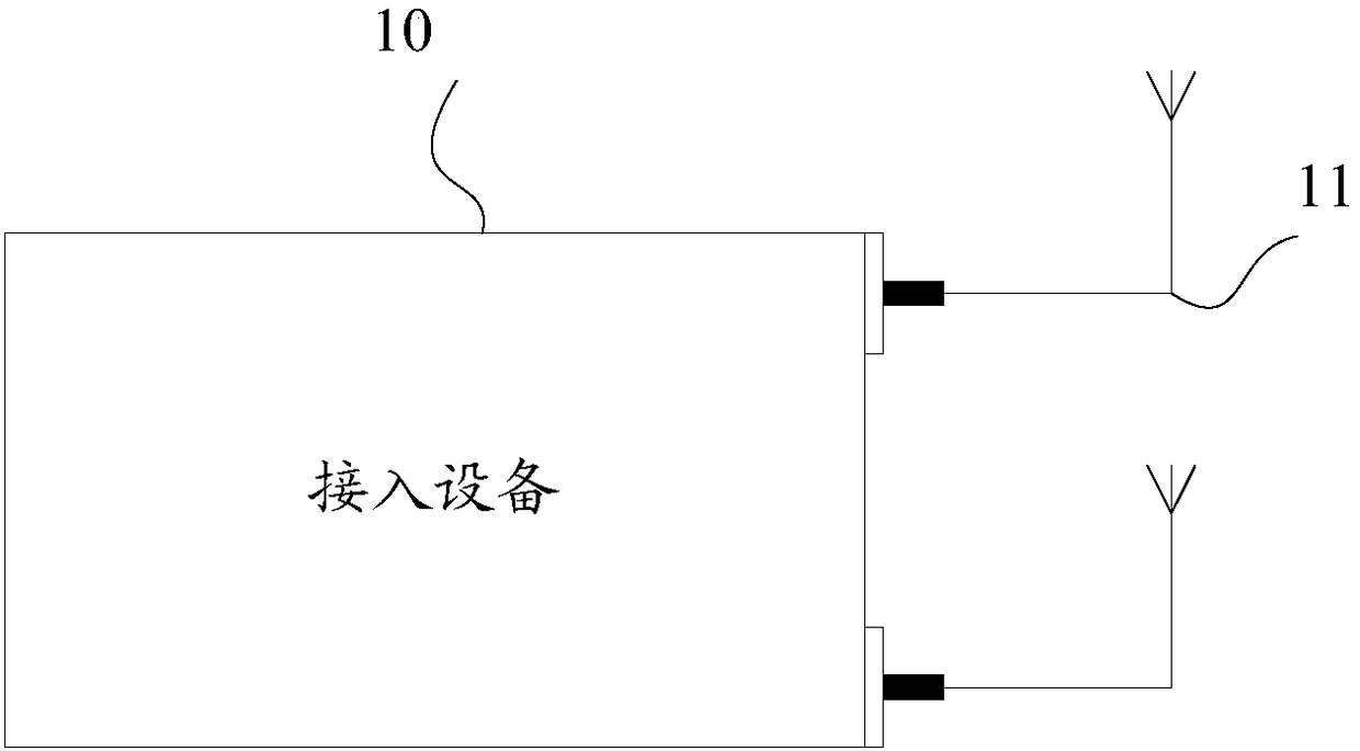
[0030] In order to solve the problem that in the prior art, when wireless network coverage is performed on multiple rooms in the network area, the high-frequency branch distributor needs to be replaced, resulting in high wireless network coverage costs, and when high-frequency signals are transmitted on coaxial cables, For the problem of large attenuation and short transmission distance, this embodiment provides a signal conversion device, please refer to Figure 4 :

[0031]The signal conversion device 40 can be applied to home network coverage. It should be understood that, in addition to the home, the signal conversion device is also used for wireless coverage in networked areas where he needs to use the network. In addition to the commonly referred to families, the network area also includes offices, and public places such as movie theaters, shopping malls, and rail trains. The signal conversion device 40 in this embodiment has significant advantages when realizing wirel...

Embodiment 2

[0049] This embodiment will continue to introduce the signal conversion device, the signal coupling device and the wireless network coverage system in the foregoing examples. The structure of the wireless network coverage system provided in this embodiment is similar to that in the first embodiment, but the signal converting device and the signal coupling device therein are different from those in the first embodiment. So first, see Figure 7 Schematic diagram of the structure of the signal conversion equipment shown:

[0050]The signal conversion device 70 includes a transceiver unit 71, a conversion unit 72, and a frequency mixing unit 73, wherein the transceiver unit 71 can still receive radio frequency signals, and the conversion unit 72 can convert the radio frequency signals received by the transceiver unit into coaxial adaptation signals . It should be understood that in many cases, there is more than one kind of radio frequency signal exchanged between the access dev...

Embodiment 3

[0058] This embodiment will introduce the signal conversion device, signal coupling device, and wireless network coverage system in the foregoing embodiments with reference to specific examples. Please refer to Figure 9 :

[0059] Figure 9 Shown is a schematic diagram of a wireless network coverage system, wherein the wireless network coverage system 9 includes an access gateway 91 , a frequency synthesizer 92 , a branch distributor 93 , a coaxial cable 94 and a coupling antenna 95 . The structure of the frequency synthesizer 92 can refer to the signal conversion device in the foregoing embodiments, and the coupling antenna 94 is a device that integrates the WLAN antenna and the signal coupling device in the foregoing examples.

[0060] The frequency synthesizer 92 is connected to the WiFi antenna interface of the access gateway 91, which can receive the radio frequency signal from the access gateway 91, and then perform down-frequency processing on the radio frequency sign...


PUM


Abstract

The embodiment of the invention provides a signal conversion device, signal coupling device and wireless network coverage system. The signal conversion device and the signal coupling device are applied between an access device and a wireless local area network antenna, through processing of the signal conversion device and the signal coupling device, it is ensured that the access device and the wireless local area network antenna can still employ radio-frequency signals to perform interaction with other external devices, and the coaxial adaptive signals passing through a branch distributer necessarily meet the requirement of a branch distributed with frequency being smaller than or equal to 1000MHz so that it is not necessary to specially replace a high-frequency branch distributer for network coverage and the problems of high cost and wasted devices caused by replacement of the device are avoided. The frequency of the coaxial adaptive signals obtained through conversion is necessarilylower than 1000MHz so as to avoid large attenuation, improve the transmission distance and provide better online experience for users when a coaxial cable is employed to transmit low-frequency signals.

Description

technical field [0001] The invention relates to the technical field of communication, in particular to a signal conversion, signal coupling device and a wireless network coverage system. Background technique [0002] With the rapid development of FTTH (Fiber To The Home, fiber-to-the-home), it is very common for home bandwidth to exceed 100M. In theory, such bandwidth can provide users with a better Internet experience. But in fact, user experience also depends on the coverage of the wireless network in the network area. The current access device 10, or home access device, such as the WiFi AP (Wireless-Fidelity Access Point, wireless fidelity access point) of ONT (Optical Network Terminal, optical network terminal) or CPE (Customer Premise Equipment, customer terminal equipment). entry point) devices such as figure 1 As shown, wireless signals are basically sent and received through an external WLAN (Wireless Local Area Networks, wireless local area network) antenna 11 to ...

Claims


Application Information

Patent Timeline
IPC IPC(8): H04B1/40H04W16/18
CPCH04B1/40H04W16/18
Inventor 张海军
Owner ZTE CORP
Why Eureka
Try Eureka