Sounding device
A sound-generating device and reinforcement layer technology, applied to sensors, electrical components, loudspeakers, etc., can solve problems such as low elastic modulus, lower listening effect, and easy deformation of the reinforcement layer, and achieve excellent high-frequency performance Effect
- Summary
- Abstract
- Description
- Claims
- Application Information
AI Technical Summary
Problems solved by technology
Method used
Image
Examples
Embodiment 1
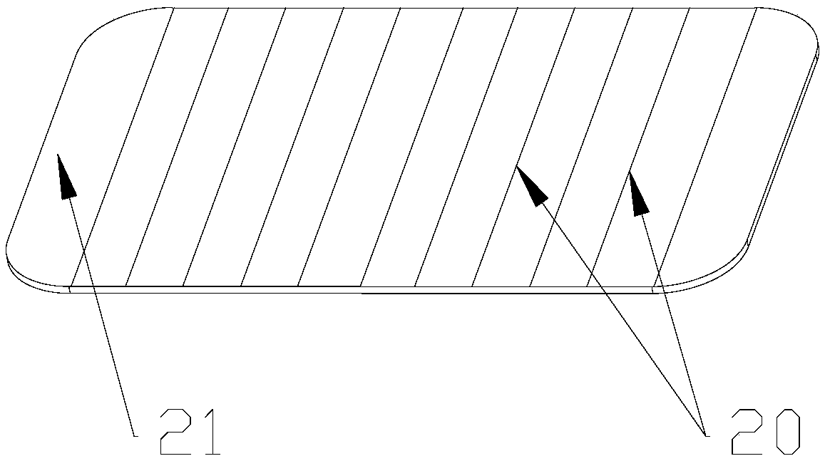
[0081] In this example, the performance of carbon fibers 20 of different diameters of the same material was tested. The carbon fiber 20 is polyacrylonitrile-based carbon fiber or pitch-based carbon fiber. See Table 1 for details.
[0082] Filament diameter / μm
Carbon fiber 20 diameter / μm
Tensile strength / GPa
Elastic modulus / GPa
6
3.1
5.89
286
7
3.6
5.45
281
8
5.0
4.46
274
11
7.0
3.79
259
13
8.5
3.46
251
[0083] Table 1 - the relationship between the diameter of the precursor, the diameter of carbon fiber 20 and the mechanical properties of carbon fiber 20
[0084] It can be seen from Table 1 that as the diameter of the carbon fiber 20 decreases, the tensile strength and elastic modulus of the carbon fiber 20 gradually increase. When the diameter of the carbon fiber 20 is less than 7.0 μm, the tensile strength and elastic modulus of the carbon fiber 20 are relatively large, re...
Embodiment 2
[0086] In this example, the diameters and mechanical properties of carbon fibers 20 of different grades and diameters are compared. See Table 2 for details.
[0087]
[0088]
[0089] Table 2 - Main mechanical properties of different grades of carbon fiber 20
[0090] It can be seen from Table 2 that the diameters of the above-mentioned various carbon fibers 20 are all within 7.0 μm, and all have high tensile strength and elastic modulus, which significantly increases the stiffness of the reinforcing layer 15 .
Embodiment 3
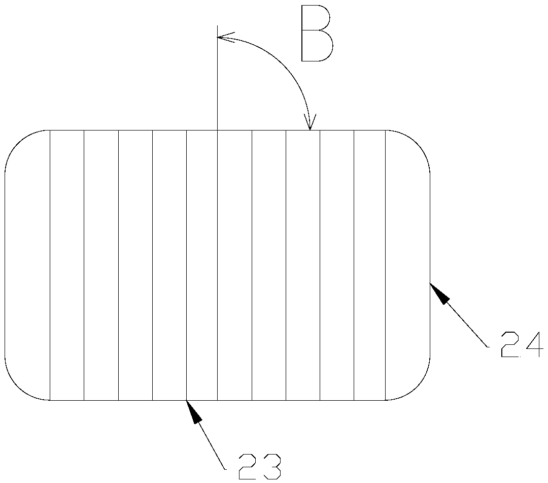
[0092] The acoustic performance of the sound generating device of the embodiment of the present invention is compared with that of the existing sound generating device. Wherein, the power of the two sound generating devices is the same. The reinforcing layer 15 of the sound generating device according to the embodiment of the present invention has a structure of unidirectional carbon fiber prepreg layer + PMI foam core layer + unidirectional carbon fiber prepreg layer. A unidirectional layer of carbon fiber prepreg sets a layer of carbon fiber. The carbon fibers have a diameter of 4-5 μm and are arranged in the same direction; the material of the reinforcing layer 15 of the existing sound generating device is aluminum foil+adhesive film+PMI foam core layer+adhesive film+aluminum foil. The size of the two reinforcing layers 15 is the same, the length of the sound generating device is 18mm, and the width is 13mm. The reinforcing layer 15 has a length of 14 mm and a width of 9 ...
PUM
 Abstract
Description
Claims
Application Information
 - R&D
- Intellectual Property
- Life Sciences
- Materials
- Tech Scout
- Unparalleled Data Quality
- Higher Quality Content
- 60% Fewer Hallucinations
Browse by: Latest US Patents, China's latest patents, Technical Efficacy Thesaurus, Application Domain, Technology Topic, Popular Technical Reports.
© 2025 PatSnap. All rights reserved.Legal|Privacy policy|Modern Slavery Act Transparency Statement|Sitemap|About US| Contact US: help@patsnap.com


