
Isolation amplifiers, proportional controlled sources and integral controlled sources with isolation amplifiers, and mutual coupler

An isolation amplifier and operational amplifier technology, applied in electronic circuits, analog signal processing devices, and circuits, can solve the problems of heavy weight, large device volume, large nonlinearity, etc., and achieve good linearity, high frequency performance, and response speed. quick effect

Active Publication Date: 2019-04-23
朱嘉慧
View PDF16 Cites 0 Cited by
  • Summary
  • Abstract
  • Description
  • Claims
  • Application Information

AI Technical Summary

Problems solved by technology

A common method to achieve isolation coupling is to use magnetic field isolation coupling, such as transformers and transformers, etc., but the DC signal cannot be transformed, and the high-frequency performance and dynamic performance are not good due to the existence of magnetic flux leakage; the voltage and current of the Hall element are used Although the transmitter can process DC signals, the problems of poor high-frequency performance and dynamic performance caused by magnetic flux leakage still exist, and such devices are large in size, heavy in weight and very difficult to integrate
Another approach is to use a photocoupler, which is a signal unidirectional device and has a large nonlinearity

Method used


Image

  • Isolation amplifiers, proportional controlled sources and integral controlled sources with isolation amplifiers, and mutual coupler
  • Isolation amplifiers, proportional controlled sources and integral controlled sources with isolation amplifiers, and mutual coupler
  • Isolation amplifiers, proportional controlled sources and integral controlled sources with isolation amplifiers, and mutual coupler

Examples


Embodiment 1

[0116] Voltage Mode Isolation Amplifier and Current Mode Isolation Amplifier

[0117] Inverting-inverting dual output, inverting-inverting-inverting dual-output, in-phase-in-phase dual-output, in-phase-inverting dual-output voltage isolation amplifier schematic diagram Figure 12a , 12b , 12c, 12d shown. The dual output voltage type isolation amplifier consists of two double phototransistor receiving optocouplers OD with the same parameters P 、OD N and two current-limiting resistors of equal value R X constitute, two optocouplers OD P and OD N The light-emitting diodes are connected in series with a current-limiting resistor R X Then connect in series in the forward direction, and the two ends are respectively connected to the 0th group of independent positive and negative symmetrical dual power supplies +V0 and -V0, and the common terminal is used as the input terminal u of the dual output voltage type isolation amplifier. i Relative to the floating ground Fgnd0 input ...

Embodiment 2

[0123] Single output proportional controlled source and dual output proportional controlled source

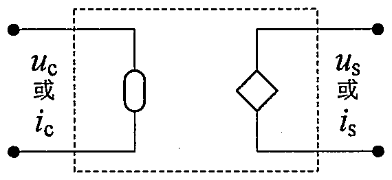
[0124] The proportional controlled source is composed of an inverting isolation amplifier or a non-inverting isolation amplifier, an input control circuit and an output conditioning circuit. The input control circuit from the input port to the isolation amplifier has two types: a current type control circuit and a voltage type control circuit. The isolation amplifier to the output port There are two types of output conditioning circuits: voltage-type conditioning circuits and current-type conditioning circuits.

[0125] The single-output proportional controlled source has a control input port and a power output port, and has four types: current-controlled voltage source, current-controlled current source, voltage-controlled voltage source and voltage-controlled current source.

[0126] The block diagram of the current-controlled voltage source using an inverting isolation ampli...

Embodiment 3

[0140] Single output integral controlled source and dual output integral controlled source

[0141] The single-output integral controlled source has a control input port and a power output port, and has four types: current integrating voltage source, current integrating current source, voltage integrating voltage source and voltage integrating current source.

[0142] The block diagram of current integrating voltage source using inverting isolation amplifier and non-inverting isolation amplifier is as follows: Figure 26a , 26b shown. The current integral voltage source is obtained by replacing the operational resistance of the current control voltage source with an operational capacitor. The input-output relationship is:

[0143]

[0144] The block diagram of the current integrating current source using the inverting isolation amplifier and the non-inverting isolation amplifier is as follows: Figure 27a , 27b shown. The current integral current source is obtained by ...


PUM


Abstract

The invention relates to isolation amplifiers, proportional controlled sources and integral controlled sources with the isolation amplifiers, and a mutual coupler, and belongs to a circuit, electroniccircuit and analog signal processing device. The isolation amplifiers are each composed of two diode or audion receiving-type photoelectric couplers with the same parameters, are each of a complimentary symmetry structure, and have excellent characteristics of direct current signal amplifying, high isolation property, alternate current signal positive and negative symmetry and quick response; theproportional controlled sources and the integral controlled sources are composed of the isolation amplifiers and operational amplifiers, and central core circuits are in mirror symmetry and have thehigh isolating property, the high linearity degree, the high operational precision and ideal input and output characteristics of the controlled sources; the mutual coupler is composed of the controlled sources and has excellent properties because of the complimentary symmetry structure of the isolation amplifiers and the mirror symmetry structure of the controlled sources, and thus the various transformation functions can be achieved; and the proportional controlled sources, the integral controlled sources and the mutual coupler are applied to single-phase, two-phase and three-phase circuits,and the rich functions of isolation, control, operation, transformation and the like are achieved.

Description

technical field [0001] The invention relates to an isolation amplifier and its proportional controlled source, integral controlled source and mutual coupler, especially the isolated amplifier constructed by using a photocoupler, its proportional controlled source, integral controlled source and the controlled source The constructed mutual coupler belongs to a circuit, an electronic circuit, and an analog signal processing device. Background technique [0002] With the development of society and technology, the application of circuits is becoming more and more common, but at the same time the circuits are becoming more and more complex, from simple couplet circuits, series-parallel conversion circuits, three-fork triangle conversion circuits to super complex circuits, from single-port circuits Network, two-port circuit network to multi-port circuit network, from single-phase circuit, two-phase circuit, three-phase circuit to multi-phase circuit, from static circuit, steady st...

Claims


Application Information

Patent Timeline
IPC IPC(8): G05F1/56
CPCG05F1/56
Inventor 朱明朱嘉慧
Owner 朱嘉慧
Learn More