Communication power supply cabinet with uniform heat dissipation

A communication power supply, uniform heat dissipation technology, applied in the direction of cooling/ventilation/heating transformation, etc., can solve the problems of affecting the operation of internal parts, damage, increase of heat of the shell, etc., to meet the requirements of use, prolong the service life, and have a large blowing area. Effect

Inactive Publication Date: 2019-02-26
郑州森之林电子科技有限公司
View PDF7 Cites 5 Cited by
  • Summary
  • Abstract
  • Description
  • Claims
  • Application Information

AI Technical Summary

Problems solved by technology

[0002] The communication power supply system is the heart of the communication system. A stable and reliable communication power supply system is the key to ensure the safe and reliable operation of the communication system. The communication circuit is interrupted and the communication system is paralyzed, resulting in great economic and social benefit losses
[0003] After the communication power supply machine works in the cabinet for a long time, it will generate a lot of heat, which will increase the heat in the casing. If the temperature is too high, it will affect the work of the internal parts. The traditional heat dissipation device dissipates heat in a fixed position, and the heat dissipation is uneven. , can not achieve full heat dissipation
[0004] For the problem of uneven heat dissipation in the communication power supply cabinet, a Chinese patent (CN206759920U) discloses a communication power supply cabinet with intelligent heat dissipation. Under the action of the gear transmission, the suction pipe is driven to rotate in the cabinet, but because the motor and gear system of the device are placed outside the cabinet, it is easy to cause damage. At the same time, the movement track of the suction pipe is a ring, and the heat dissipation area is relatively limited.

Method used


Image

  • Communication power supply cabinet with uniform heat dissipation
  • Communication power supply cabinet with uniform heat dissipation
  • Communication power supply cabinet with uniform heat dissipation

Examples


Embodiment Construction

[0020] The technical solution of this patent will be further described in detail below in conjunction with specific embodiments.

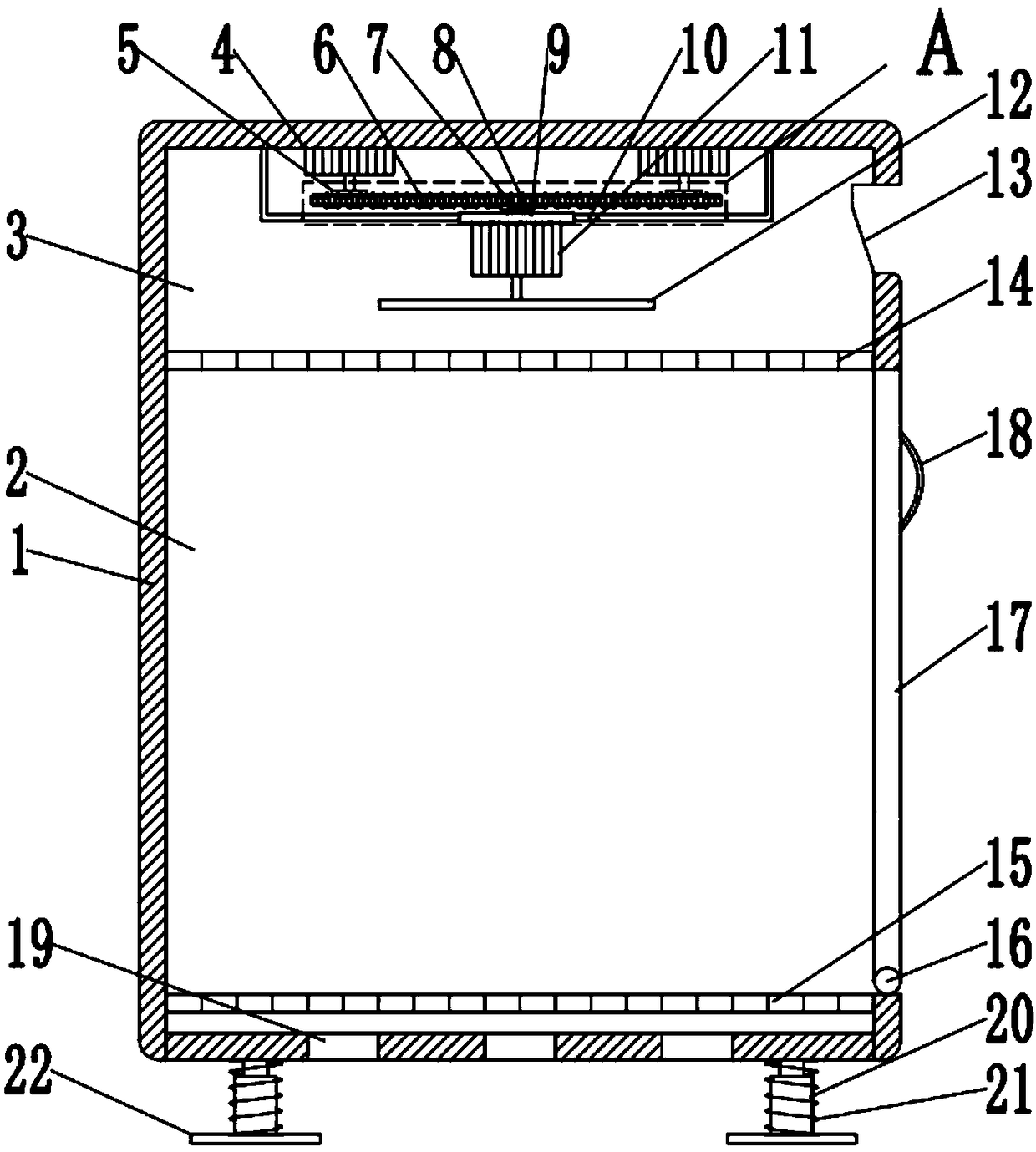
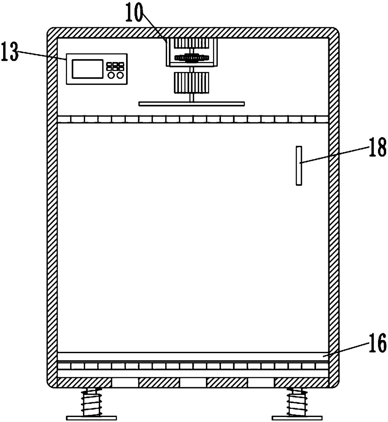
[0021] see figure 1 and image 3 , a communication power supply cabinet with uniform heat dissipation, including a housing 1, a plurality of ventilation holes 19 are provided at the bottom of the housing 1 to facilitate heat dissipation in the housing 1, a second mesh 15 is fixedly installed inside the housing 1, The first mesh 14 is fixedly installed above the second mesh 15, and the first mesh 14 divides the housing 1 into a storage compartment 2 and a fan compartment 3. A rotating shaft 16 is installed on the right side of the storage compartment 2, and the rotating shaft 16 is rotatably connected. There is a dodge door 17, the dodge door 17 top is provided with a handle 18, the dodge door 17 can be opened by the handle 18, and the access in the storage room 2 is carried out. Two power motors 4 are fixedly connected, and the four corners of th...


PUM


Abstract

The invention discloses a communication power supply cabinet with uniform heat dissipation, which includes a housing. A first mesh sheet is fixedly mounted inside the housing and divides the housing into a storage bin and a fan bin; two power motors are fixedly connected to the inside of a top plate of the fan bin; sprocket wheels are fixedly connected to the output shafts of the power motors; a chain sleeves the outer sides of the sprocket wheels; a trapezoidal slider is fixedly connected at the bottom of the chain; a fixing frame is slidably connected to the bottom of the trapezoidal slider;a motor base is fixedly connected to the bottom of the fixing frame; a fan motor is installed at the bottom of the motor base; fan blades are fixedly connected to the output shaft of the fan motor. When the power motors are controlled to rotate, the chain is driven to rotate on the two sprocket wheels and the fan structure fixedly connected to the chain reciprocates left and right in the fan binso as to carry out omni-directional air blowing and heat dissipation to the storage bin. The device structure is arranged in the housing body to avoid damage caused by external factors, so that the service life of parts and components is prolonged; the communication power supply cabinet has large air blowing area and uniform heat dissipation and meets the service requirements.

Description

technical field [0001] The invention relates to a communication device, in particular to a communication power cabinet with uniform heat dissipation. Background technique [0002] The communication power supply system is the heart of the communication system. A stable and reliable communication power supply system is the key to ensure the safe and reliable operation of the communication system. The communication circuit is interrupted and the communication system is paralyzed, resulting in great economic and social benefit losses. [0003] After the communication power supply machine works in the cabinet for a long time, it will generate a lot of heat, which will increase the heat in the casing. If the temperature is too high, it will affect the work of the internal parts. The traditional heat dissipation device dissipates heat in a fixed position, and the heat dissipation is uneven. , unable to achieve full heat dissipation. [0004] For the problem of uneven heat dissipa...

Claims


Application Information

Patent Timeline
Patent Type & Authority Applications(China)
IPC IPC(8): H05K7/20
Inventor 刘莉
Owner 郑州森之林电子科技有限公司
Why Eureka
Try Eureka