A non-reflective iris information measurement system

An information measurement and iris technology, which is applied in the fields of eye testing equipment, medical science, diagnosis, etc., can solve the problems affecting the acquisition effect, etc., and achieve the effect of improving the acquisition resolution

Active Publication Date: 2019-11-26
天目爱视(北京)科技有限公司
View PDF6 Cites 0 Cited by
  • Summary
  • Abstract
  • Description
  • Claims
  • Application Information

AI Technical Summary

Problems solved by technology

But even so, the image of the light source will still affect the collection effect to a certain extent, and a complex adjustment process is required to make the image of the light source at the specified position

Method used


Image

  • A non-reflective iris information measurement system
  • A non-reflective iris information measurement system
  • A non-reflective iris information measurement system

Examples


Embodiment 1

[0071] Embodiment 1 (separator)

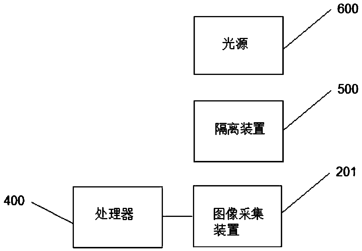
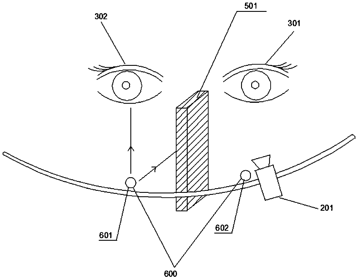
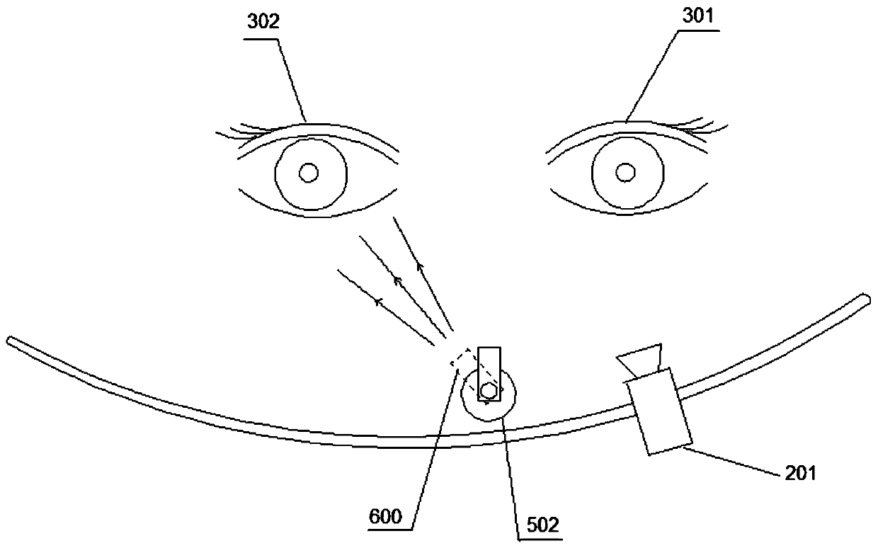
[0072] It includes image acquisition device 201, isolation device 500, light source 600, processor 400, target iris 301, and non-target iris 302 are different eyes of the same person.

[0073] The image acquisition device 201 may be a multi-camera matrix, a fixed single camera, a video camera, a rotating single camera, and other devices capable of image acquisition. It is used to capture an image of the target iris 301 . When performing two-dimensional iris collection, only two-dimensional images of the iris need to be collected and sent to the processor 400 for image processing, measurement and identification. However, two-dimensional iris measurement and recognition can no longer meet the current high-precision and high-accuracy collection, measurement, and recognition requirements. Therefore, the present invention also proposes to use a virtual camera matrix to realize three-dimensional iris collection. At this time, the image acquisiti...

Embodiment 2

[0081] In order to solve the above technical problems, an embodiment of the present invention provides an iris 3D information acquisition / measurement device. Such as Figure 4 As shown, it specifically includes: a track 101, an image acquisition device 201, an image processing device 100, a mechanical moving device 102, the image acquisition device 201 is installed on the mechanical moving device 102, and the mechanical moving device 102 can move along the track 101, so that the image acquisition The collection area of ​​the device 201 is constantly changing, forming multiple collection areas in different spatial positions over a period of time, forming a collection matrix, but at a certain moment there is only one collection area, so the collection matrix is ​​"virtual". Since the image acquisition device 201 is generally composed of cameras, it is also called a virtual camera matrix. However, the image acquisition device 201 can also be a video camera, CCD, CMOS, camera, mo...

Embodiment 3

[0112] Embodiment 3 (single-axis rotating iris collection)

[0113] The small-range, small-depth target object 3 has a smaller horizontal size compared with the camera acquisition range, and a smaller size along the depth direction of the camera, that is, the target object 3 has less information in the depth direction. In this application, although a single-camera system that moves in a large range through rails, robotic arms, etc. can also collect multi-angle images of the target object 3 to synthesize 3D point clouds or images, but these devices are more complicated, which reduces reliability. . And large movements lead to extended acquisition times. And because of its large size, it cannot be applied to many occasions (such as access control systems).

[0114] The small-scale and small-depth target 3 has its own unique characteristics, which require the acquisition / measurement equipment to be small in size, high in reliability, and fast in acquisition speed, especially ...


PUM


Abstract

The invention provides a non-reflective iris information measurement system and collection system. The measurement system includes: a light source for providing illumination to non-target iris; an isolation device for preventing light from the light source from entering the target iris; a collection device for The target iris information is collected; the non-target iris and the target iris respectively belong to different eyes of the same person; the measuring device measures its size according to the iris information. For the first time, it was found that when one eye of a person receives light, the other eye will have a similar reaction to the illuminated eye, and it was realized for the first time that this phenomenon can be used for the supplementary light process of iris collection.

Description

technical field [0001] The invention relates to the technical field of measurement, in particular to the technical field of iris size and shape dimension measurement. Background technique [0002] In order to increase the effective area during iris acquisition and measurement, the pupil needs to be narrowed. The current common way of miosis includes supplementary light during iris measurement, that is, using a certain amount of light to increase the amount of light entering the pupil, thereby causing physiological miosis. This process necessarily requires the use of a light source. [0003] However, the lens in front of the eyeball is a transparent object. When the light source illuminates the eye, it will reflect the light of the light source, thereby forming an image of the light source on the eye. This image of the light source will affect the collection of the iris. When the image position of the light source coincides with the iris, iris information cannot be collecte...

Claims


Application Information

Patent Timeline
Patent Type & Authority Patents(China)
IPC IPC(8): A61B3/14A61B3/10A61B3/00
CPCG06V40/19
Inventor 左忠斌左达宇
Owner 天目爱视(北京)科技有限公司
Why Eureka
Try Eureka