
A mounting positioning clamping device

A clamping device, installation and positioning technology, applied in the field of machining, can solve the problems of incompatibility and the large space occupied by the combined fixture

Active Publication Date: 2020-10-30
AVIC BEIJING AERONAUTICAL MFG TECH RES INST
View PDF5 Cites 0 Cited by
  • Summary
  • Abstract
  • Description
  • Claims
  • Application Information

AI Technical Summary

Problems solved by technology

The combined fixture takes up a lot of space, and generally only one specific position can be processed after the part is clamped, which is not suitable for the current multi-coordinate machining center.

Method used


Image

  • A mounting positioning clamping device
  • A mounting positioning clamping device
  • A mounting positioning clamping device

Examples


Embodiment Construction

[0022] In order to make the technical solutions and advantages in the embodiments of the present application clearer, the exemplary embodiments of the present application will be further described in detail below in conjunction with the accompanying drawings. Apparently, the described embodiments are only part of the embodiments of the present application, and Not an exhaustive list of all embodiments. It should be noted that, in the case of no conflict, the embodiments in the present application and the features in the embodiments can be combined with each other.

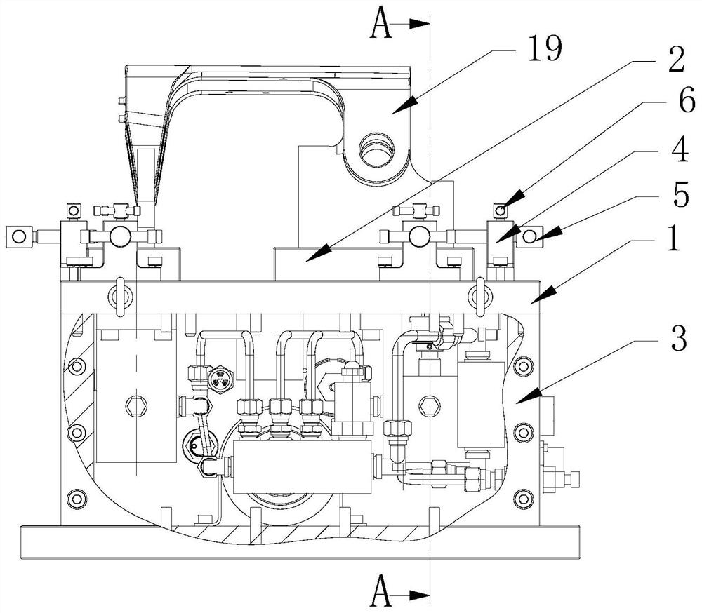
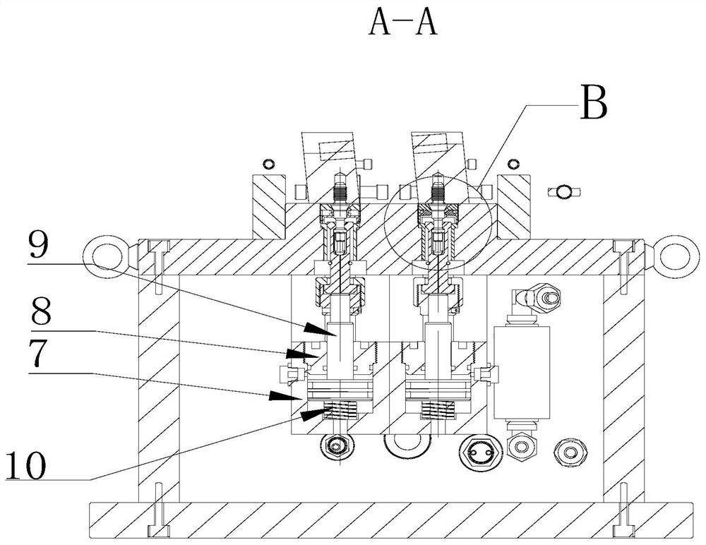
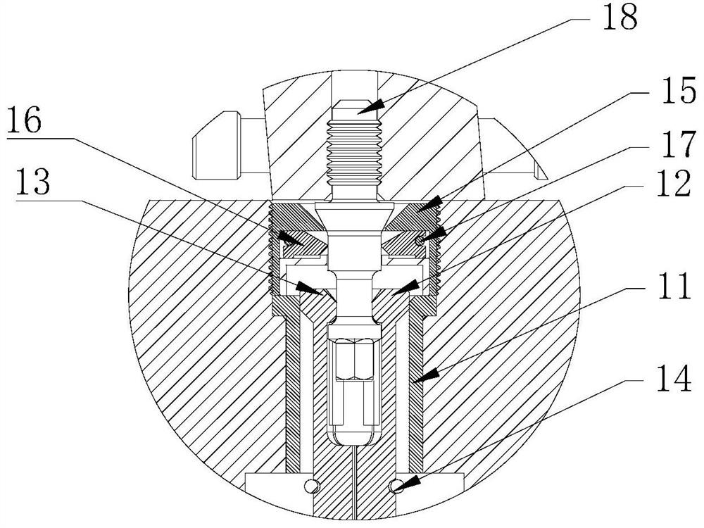
[0023] Such as Figure 1 to Figure 3 As shown, this embodiment proposes an installation, positioning and clamping device, the device includes a support plate 1 and a tensioning mechanism, the top of the support plate 1 is provided with a boss 2, and the boss 2 is used to support the Part 19, the boss 2 is provided with a through hole, and the pull stud 18 at the bottom of the part 19 to be processed passes through...


PUM


Abstract

The invention provides a mounting and positioning clamping device. The device comprises a supporting plate and tensioning mechanisms; the top of the supporting plate is provided with bosses, the bosses are used for supporting a to-be-machined part, through holes are formed in the bosses, pulling nails at the bottom of the to-be-machined part penetrate through the through holes to be connected to the tensioning mechanisms, and the tensioning mechanisms are used for downwards tensioning the pulling nails at the bottom of the to-be-machined part. According to the device, the tensioning mechanismsare connected to the pulling nails of the to-be-machined part, and the to-be-machined part is stably fixed on the supporting plate through the downward tensioning force, so that a machine tool can conveniently machine the to-be-machined part. The device has the advantage of being saving in the mounting and fixing time of the to-be-machined part, suitable for part machining and application for batch manufacturing, and especially suitable for automatic clamping and dismounting of parts on a numerical control machining center.

Description

technical field [0001] The present application relates to the field of mechanical processing, and in particular to an installation, positioning and clamping device. Background technique [0002] Existing joint parts processing generally adopts mechanical combination fixtures, and uses pressure plate fixtures to fix the parts on the machine tool combination fixtures in the form of pressure plate screws. It is usually operated by hand and is suitable for processing on ordinary manual machine tools. The combined fixture takes up a lot of space, and generally only one specific position can be processed after the part is clamped, which is not suitable for working on the current multi-coordinate machining center. Contents of the invention [0003] To solve one of the above technical problems, the present invention provides an installation positioning and clamping device. [0004] An embodiment of the present invention provides an installation, positioning and clamping device, ...

Claims


Application Information

Patent Timeline
Patent Type & Authority Patents(China)
IPC IPC(8): B23Q3/00
CPCB23Q3/00B23Q2703/04
Inventor 张书生冷军梁岱春孙晋豪
Owner AVIC BEIJING AERONAUTICAL MFG TECH RES INST
Learn More