Tool changing processing method of big cutters and small cutters in machining center

A processing center and processing method technology, applied to metal processing equipment, metal processing machine parts, manufacturing tools, etc., can solve problems such as long time and reduced processing efficiency, and achieve reasonable method design, good use effect, and improved efficiency. Effect

Inactive Publication Date: 2019-03-01
SHANGHAI SIGMA MACHINE TOOL
View PDF6 Cites 3 Cited by
  • Summary
  • Abstract
  • Description
  • Claims
  • Application Information

AI Technical Summary

Problems solved by technology

[0004] Since the radii of large and small knives are different, it is necessary to plan the placement in the tool magazine or tool chain to avoid space interference between large knives and small knives. When tools with different radii need to be used, the knives need to be replaced. The existing replacement The knife method is to stop the machine and then manually change the knife. This method takes a long time and reduces the processing efficiency.

Method used


Image

  • Tool changing processing method of big cutters and small cutters in machining center
  • Tool changing processing method of big cutters and small cutters in machining center

Examples


Embodiment 1

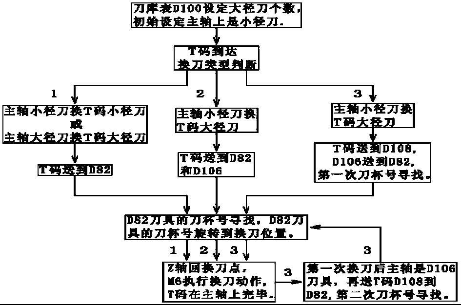
[0022] A tool change processing method for large and small knives in a machining center, the specific steps are as follows:

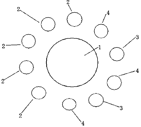
[0023] Step 1: Set the number of large knives and small knives in the tool magazine. The adjacent sides of the large knives in the tool magazine must be empty. The diameter of the large knife should not exceed twice the maximum diameter of the small knives. The number of small knives in the tool magazine must be greater than the number of large knives. Twice and add one more, to judge whether the spindle is a large tool or a small tool, and judge whether the tool pocket where the target tool T0 is located is in the large tool pocket area or in the small tool pocket area;

[0024] Step 2: If the main shaft is a small tool, T0 is located in the area of ​​the small tool pocket, and the tool is changed directly; if the main shaft is a large knife, T0 is located in the area of ​​the large tool pocket, and the tool is changed directly; Change the small tool i...

Embodiment 2

[0026] A tool change processing method for large and small knives in a machining center, the specific steps are as follows:

[0027] Step 1. Set the number of large tools and small tools in the tool magazine. Large tools must be placed in the area of ​​large tool pockets in the tool magazine, and small tools must be placed in the area of ​​​​large tool pockets or small tool pockets. The initially set spindle tools must be non-large tools. Pre-select Tool processing, judging whether the spindle is a large knife or a small knife, and judging whether the tool pocket where the target tool T0 is located is in the large tool pocket area or in the small tool pocket area;

[0028] Step 2: If the main shaft is a small tool, T0 is located in the area of ​​the small tool pocket, and the tool is changed directly; if the main shaft is a large knife, T0 is located in the area of ​​the large tool pocket, and the tool is changed directly; Change the small tool in the sleeve area to the main s...


PUM


Abstract

The invention discloses a tool changing processing method for large cutters and small cutters in a machining center. The tool changing processing method comprises the specific steps that 1, the numberof large cutters and small cutters in the tool magazine is set, whether the cutter on the main shaft is a large cutter or a small cutter is judged, whether the cutter sleeve of a target cutter T0 isin a large cutter sleeve area or a small cutter sleeve area is judged; 2, if the cutter on the main shaft is a small cutter, and T0 is located in the small cutter sleeve area, the cutter is directly replaced; if the cutter on the main shaft is a larger cutter, T0 is located in the large cutter sleeve area, and then the cutter is directly replaced; if the cutter on the main shaft is a large cutter,T0 is located in the small cutter sleeve area, a small cutter in the large cutter sleeve area is changed to the main shaft, and then the small cutter on the main shaft is replaced by T0. The method is reasonable in design, the cutter on the main shaft can be directly replaced with the target cutter in the tool magazine, manual replacement is not needed, the tool replacement efficiency is improved, and the use effect is good.

Description

technical field [0001] The invention relates to the field of tool change in machining, in particular to a tool change processing method for large and small knives in a machining center. Background technique [0002] Machining is the abbreviation of mechanical processing, which refers to the processing technology of removing material through precise mechanical processing. Machining mainly includes two categories: manual processing and numerical control processing. Manual processing refers to the method of processing various materials by mechanical workers manually operating mechanical equipment such as milling machines, lathes, drilling machines, and sawing machines. Manual processing is suitable for small batch and simple part production. CNC machining refers to the use of CNC equipment by mechanical workers for processing. CNC machining processes workpieces in a continuous manner, which is suitable for large quantities of parts with complex shapes. [0003] The cutting t...

Claims


Application Information

Patent Timeline
Patent Type & Authority Applications(China)
IPC IPC(8): B23Q3/155
CPCB23Q3/15506
Inventor 林荣张辉
Owner SHANGHAI SIGMA MACHINE TOOL
Why Eureka
Try Eureka