Spherical self-cleaning road reflecting mirror

A mirror, self-cleaning technology, applied in the field of municipal transportation, can solve the problems of easy dust accumulation, driver visual error, affecting the use effect, etc., to achieve the effect of increasing cleaning frequency, improving driving safety, and uniform surface

Active Publication Date: 2019-03-01
嘉兴锐星光学仪器有限公司
View PDF6 Cites 5 Cited by
  • Summary
  • Abstract
  • Description
  • Claims
  • Application Information

AI Technical Summary

Problems solved by technology

However, during the use of the road reflector, its surface is prone to dust accumulation, which affects the use effect, and the dust removal device of the existing self-cleaning reflector is generally arranged on the surface of the reflector, so that part of the reflector is blocked, which is easy for drivers. Produce visual errors and affect the normal use of the mirror

Method used


Image

  • Spherical self-cleaning road reflecting mirror
  • Spherical self-cleaning road reflecting mirror
  • Spherical self-cleaning road reflecting mirror

Examples


Embodiment 1

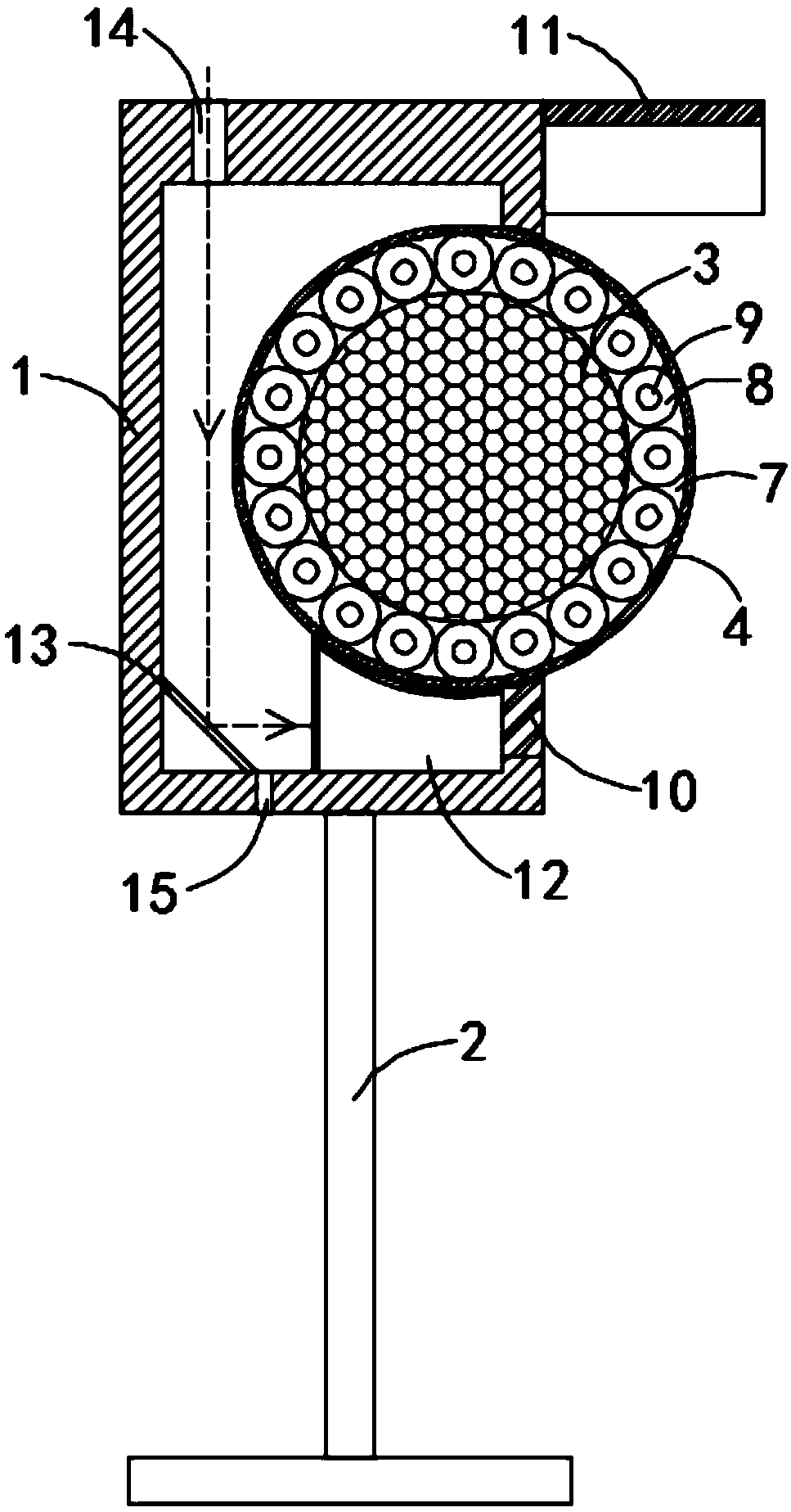
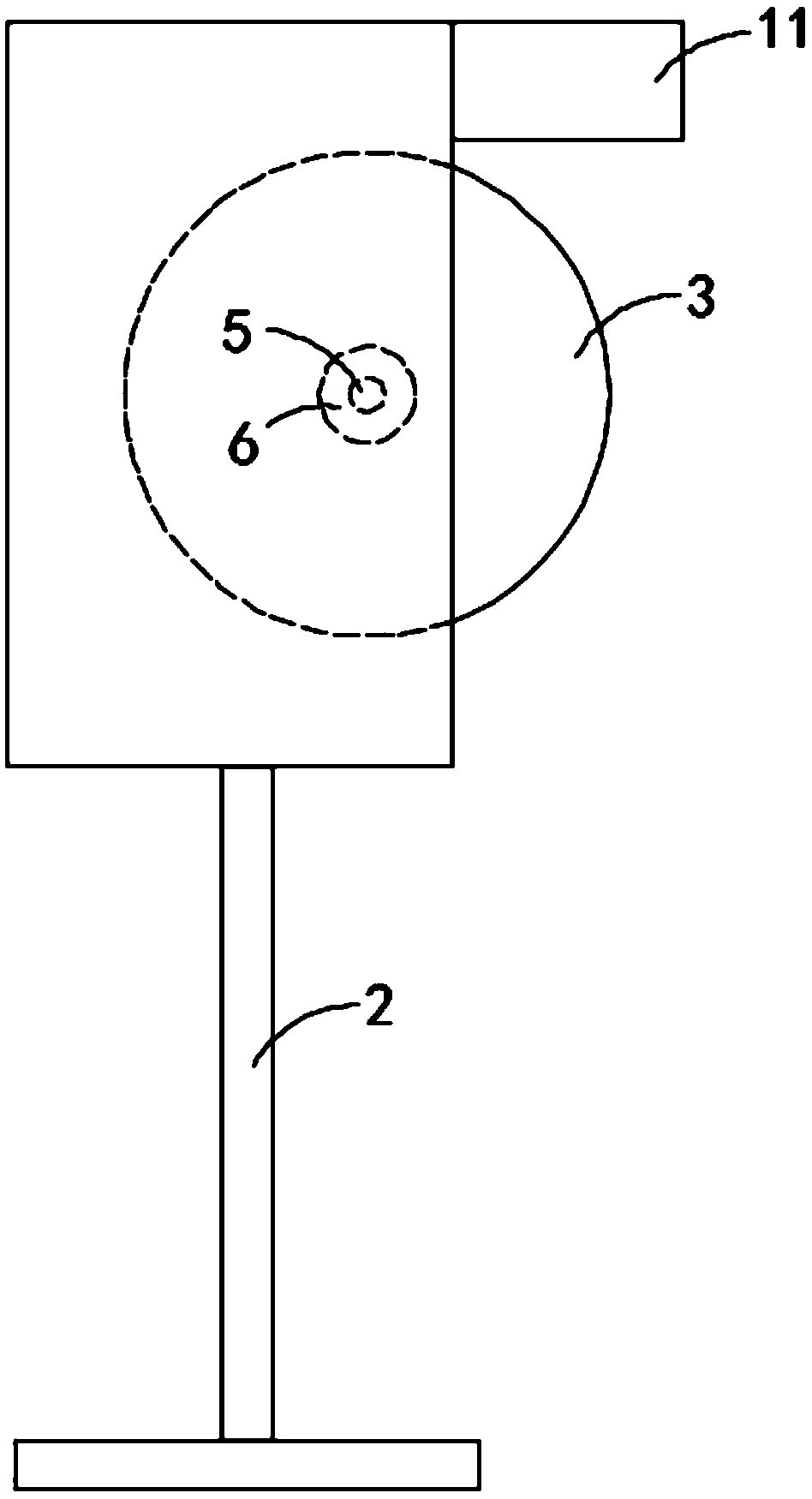
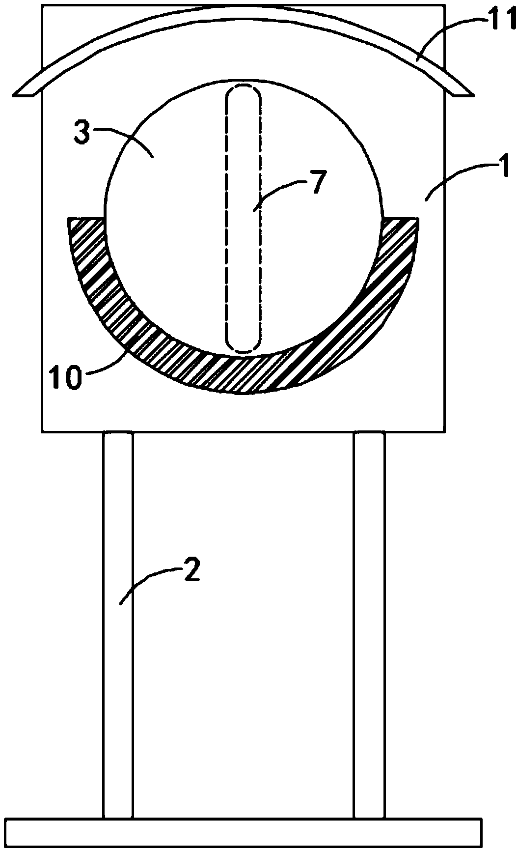
[0017] Such as Figure 1-3 As shown, a spherical self-cleaning road reflector includes a casing 1, the lower end of the casing 1 is fixedly connected with a base 2, and a sphere 3 is arranged inside the casing 1, and the sphere 3 is made of light material to reduce driving resistance , the surface of the sphere 3 is provided with a reflective layer 4, the reflective layer 4 can be a metal-plated reflective film, the inner wall of the housing 1 is fixedly connected with a fixed shaft 5, and the sphere 3 is rotationally connected with the fixed shaft 5 through a one-way bearing 6. It is illustrated that under the action of the one-way bearing 6, the part of the ball 3 outside the housing 1 can be rotated from top to bottom, and the ball 3 is provided with an annular channel 7 orthogonal to the fixed shaft 5, and the annular channel 7 is In the channel 7, heat-expanding balls 8 are closely arranged. The heat-expanding balls 8 can be made of rubber, and the interior is filled with...

Embodiment 2

[0021] Such as Figure 4 As shown, the difference between this embodiment and Embodiment 1 is that: a rotating shaft 16 is fixedly connected to the side wall of the sphere 3 away from the fixed shaft 5, and the other end of the rotating shaft 16 runs through the housing 1 and is fixedly connected to a wind wheel 17. , the direction of rotation of the wind wheel 17 is consistent with the direction of rotation of the one-way bearing.

[0022] In this embodiment, when the wind blows, the wind wheel 17 is driven by the wind to rotate, and the wind wheel 17 drives the sphere 3 to rotate through the rotating shaft 16, which can also have a cleaning effect on the sphere 3, increase the scope of application of the sphere 3, and increase How often the sphere 3 is cleaned.


PUM


Abstract

The invention belongs to the field of municipal traffic and in particular relates to a spherical self-cleaning road reflecting mirror. The spherical self-cleaning road reflecting mirror comprises a shell; a base is fixedly connected to the lower end of the shell; a sphere is arranged in the shell; a light reflecting layer is arranged on the surface of the sphere; a fixing shaft is fixedly connected to the internal side wall of the shell; the sphere is rotationally connected with the fixing shaft through a one-way bearing; an annular passage orthogonal to the fixing shaft is formed in the sphere; thermal expansion balls are closely arranged in the annular passage; counterweight blocks are fixedly connected to the interior of the thermal expansion balls; an opening matched with the sphere isformed in the side wall of the shell; ash cleaning cotton is embedded in the lower side wall of the opening; a rain shade is fixedly connected to the side wall of the shell; a heat collecting block is fixedly connected to the internal bottom surface of the shell; a plane reflecting mirror is arranged on one side of the heat collecting block; and an included angle between the plane reflecting mirror and the bottom side wall of the shell is 45 degrees. According to the spherical self-cleaning road reflecting mirror, the surface of the reflecting mirror can be cleaned by using solar energy and wind energy, and the light reflecting effect of the reflecting mirror cannot be affected.

Description

technical field [0001] The invention belongs to the field of municipal traffic, in particular to a spherical self-cleaning road reflector. Background technique [0002] Road reflector is a device used for road reflection, which can help drivers understand the information of oncoming vehicles and improve the safety performance of driving on curves. However, during the use of the road reflector, its surface is prone to dust accumulation, which affects the use effect, and the dust removal device of the existing self-cleaning reflector is generally arranged on the surface of the reflector, so that part of the reflector is blocked, which is easy for drivers. A visual error is generated, which affects the normal use of the reflector. [0003] For this reason, we propose a spherical self-cleaning road reflector to solve the above problems. Contents of the invention [0004] The object of the present invention is to solve the above problems and provide an energy-saving and envir...

Claims


Application Information

Patent Timeline
Patent Type & Authority Applications(China)
IPC IPC(8): E01F9/608B08B11/00B08B1/02
CPCB08B1/006B08B1/02B08B11/00E01F9/608
Inventor 张登柏
Owner 嘉兴锐星光学仪器有限公司
Why Eureka
Try Eureka