Rapid drying fan for workshop ground painting

A fast-drying, ground-based technology, applied in the direction of mechanical equipment, pre-treated surfaces, machines/engines, etc., can solve problems such as unfavorable production, short construction period, time-consuming, etc., and achieve the effect of improving drying efficiency and speeding up the working process

Active Publication Date: 2019-03-01
九安信息科技(徐州)有限责任公司
View PDF8 Cites 3 Cited by
  • Summary
  • Abstract
  • Description
  • Claims
  • Application Information

AI Technical Summary

Problems solved by technology

[0003] There is often a layer of floor paint on the floor of the factory building. Brushing the floor paint on the cement floor is both beautiful and hygienic. However, at present, after the floor paint is painted, it is often kept in a natural way of ventilation and drying. For some parts, the construction period is relatively short, or For those who are in a hurry to use the factory area, natural drying will inevitably have a time-consuming problem, which is not conducive to early production

Method used


Image

  • Rapid drying fan for workshop ground painting
  • Rapid drying fan for workshop ground painting
  • Rapid drying fan for workshop ground painting

Examples


Embodiment 1

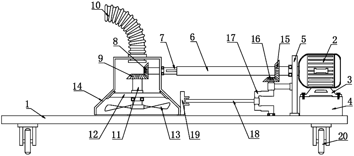
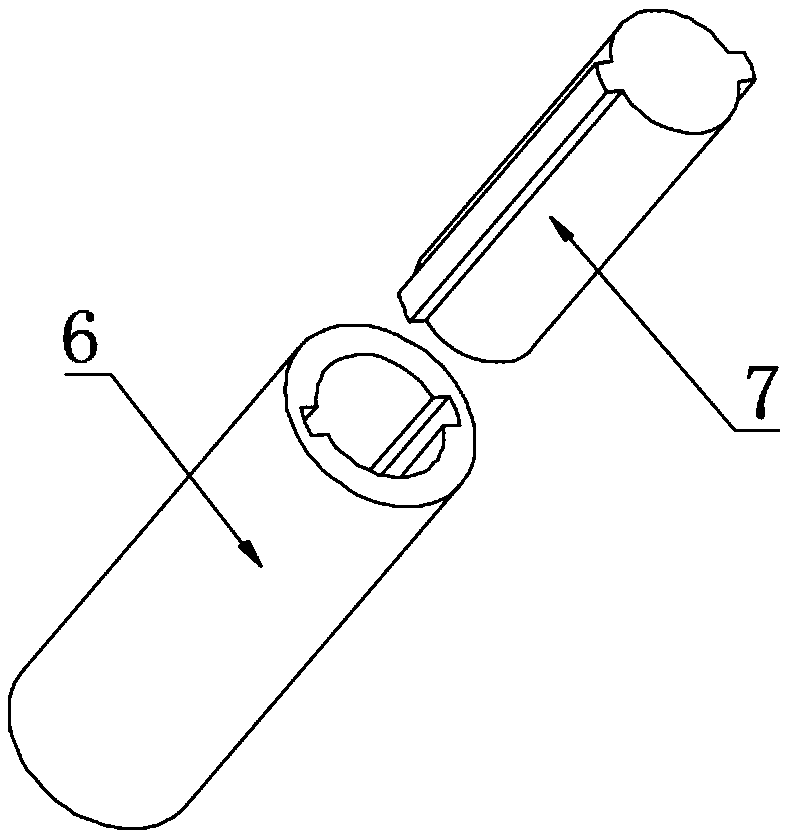
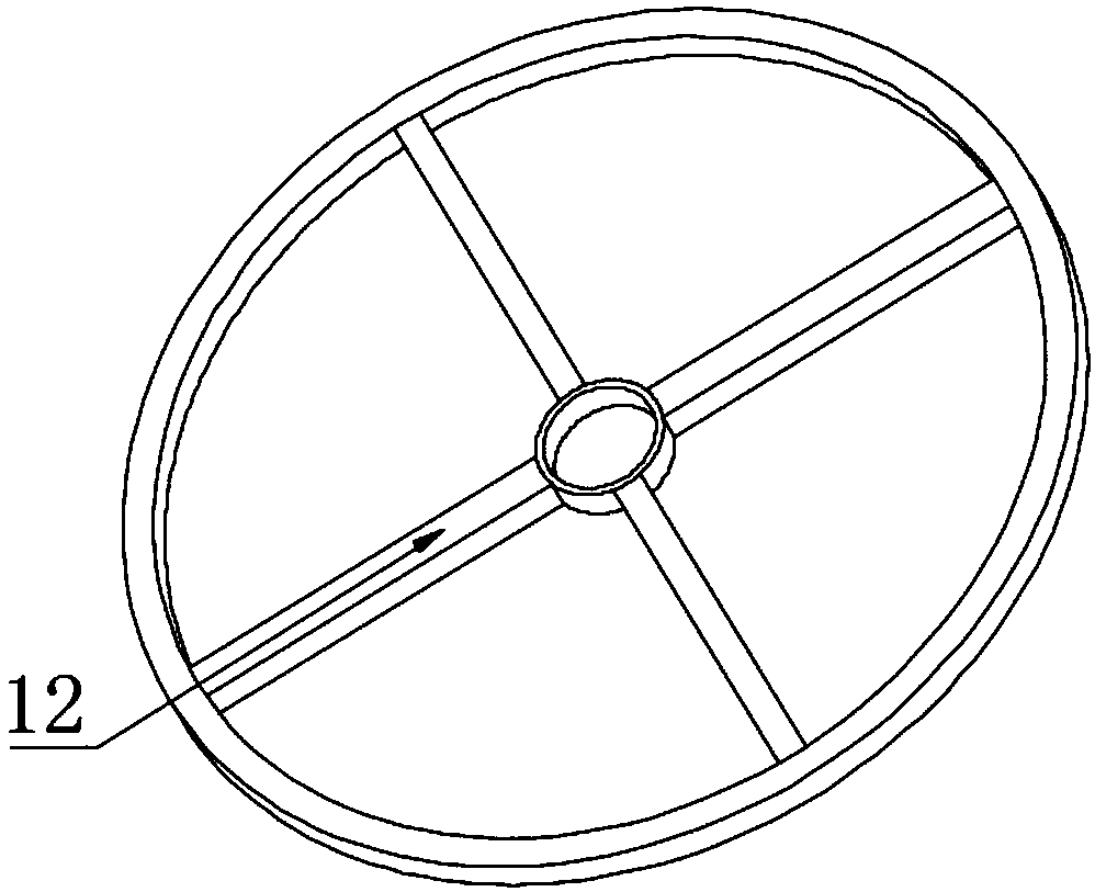
[0020] see Figure 1~3 , in an embodiment of the present invention, a quick-drying fan for painting the floor of a factory building includes a trolley plate 1, an output shaft 6, a driven shaft 7, a fan 13, a crankshaft 17, and a connecting rod 18; the four corners of the lower surface of the trolley plate 1 Both are fixed with a wheel frame, and the wheel frame is connected with the roller 20 through the rotation of a pin shaft. It should be noted that a plurality of through grooves or through holes are provided on the trolley plate 1, and a drive motor 2 is arranged on one side of the trolley plate 1, and the drive motor 2 wires are connected to the power supply and the switch, and the lower part of the drive motor 2 is fixedly connected to the motor base 3, and the lower part of the motor base 3 is fixedly connected to the battery 4 through bolts, wherein the battery 4 is a rechargeable battery, and its rear part has a charging port and an indicator light. The storage batte...

Embodiment 2

[0024] In order to make the technical solutions in this application more detailed and complete, now some supplements and explanations are made on the basis of the above-mentioned embodiment 1, so that the disclosure of the technical means adopted in this application is more sufficient, specifically, the supplements and explanations Part of the technical feature is that the rear of the trolley board 1 is fixedly connected with a handle, the handle is covered with a rubber sleeve, the bearing at the lower part of the handle is rotatably connected to the steering wheel, the steering wheel is rotatably connected to the wheel frame, and the wheel frame bearing is rotatably connected to the lower part of the trolley board 1. On the surface, the trolley board 1 is pushed forward by the handle, so as to realize the function of moving and drying. At the same time, the traveling direction of the trolley board 1 is controlled by the steering wheel connected by rotation, so as to realize th...


PUM


Abstract

The invention discloses a rapid drying fan for workshop ground painting. Wheel frames are fixed to the four corners of the lower surface of a trolley plate, rollers are rotatably connected to the wheel frames through pin shafts, a driving motor is arranged above one side of the trolley plate, a partition board is arranged on the side of the driving motor, the lower end of the partition board is fixed to the upper surface of the trolley plate, the output end of the driving motor is rotatably connected with an output shaft, one side of the output shaft is sleeved with a driven shaft, the outputshaft is a hollow shaft, two grooves are symmetrically formed in the inner wall of the output shaft, two symmetric strip convex strips are arranged on the outer surface of the driven shaft and are embedded in the grooves in the inner wall of the output shaft, one side of the driven shaft penetrates the upper wall of the fan shell and is in bearing rotation connection with the fan shell, the end ofthe driven shaft is fixedly connected with a first conical gear, the lower portion of the first conical gear is engaged with a second conical gear, the center of the lower of the second conical gearis fixedly connected with a rotating shaft, the middle of the rotating shaft is in bearing rotation connection with a holder, a corrugated hose is fixed to the upper portion of the fan shell in a communication manner, and the lower end of the rotating shaft is fixedly connected with an air fan.

Description

technical field [0001] The invention relates to construction equipment, in particular to a fast drying blower for painting the floor of a factory building. Background technique [0002] Most of the factory buildings are found in light industry, electronics, instrumentation, communication, medicine and other industries. The floors of such factory buildings are generally not very high. Their lighting design is similar to that of common scientific research and laboratory buildings, and fluorescent lighting solutions are mostly used. Production plants in machining, metallurgy, textile and other industries are generally single-story industrial buildings, and according to production needs, more multi-span single-story industrial buildings, that is, multi-span factory buildings arranged in parallel next to each other. The needs can be the same or different. [0003] There is often a layer of floor paint on the floor of the factory building. Brushing the floor paint on the cement f...

Claims


Application Information

Patent Timeline
Patent Type & Authority Applications(China)
IPC IPC(8): F04D25/08F04D25/06F04D25/02F04D25/10B05D3/04
CPCB05D3/0406F04D25/02F04D25/0673F04D25/08F04D25/10
Inventor 许建林
Owner 九安信息科技(徐州)有限责任公司
Why Eureka
Try Eureka