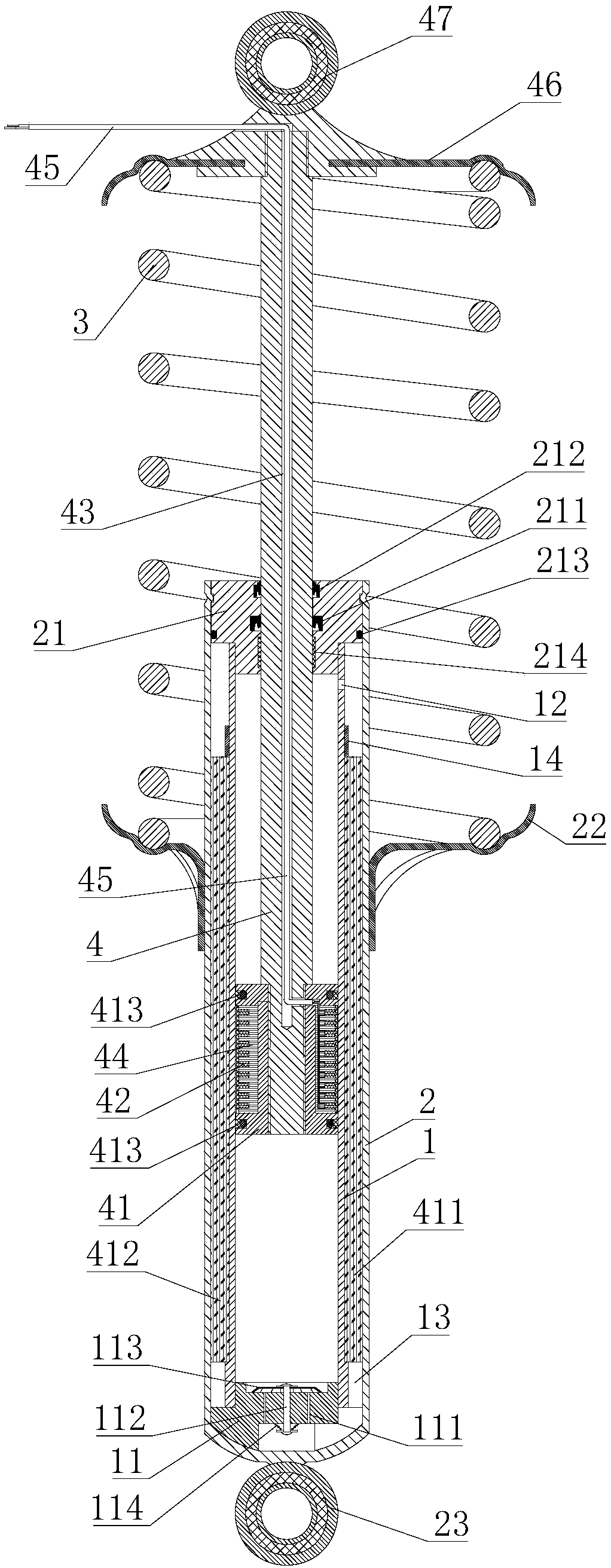
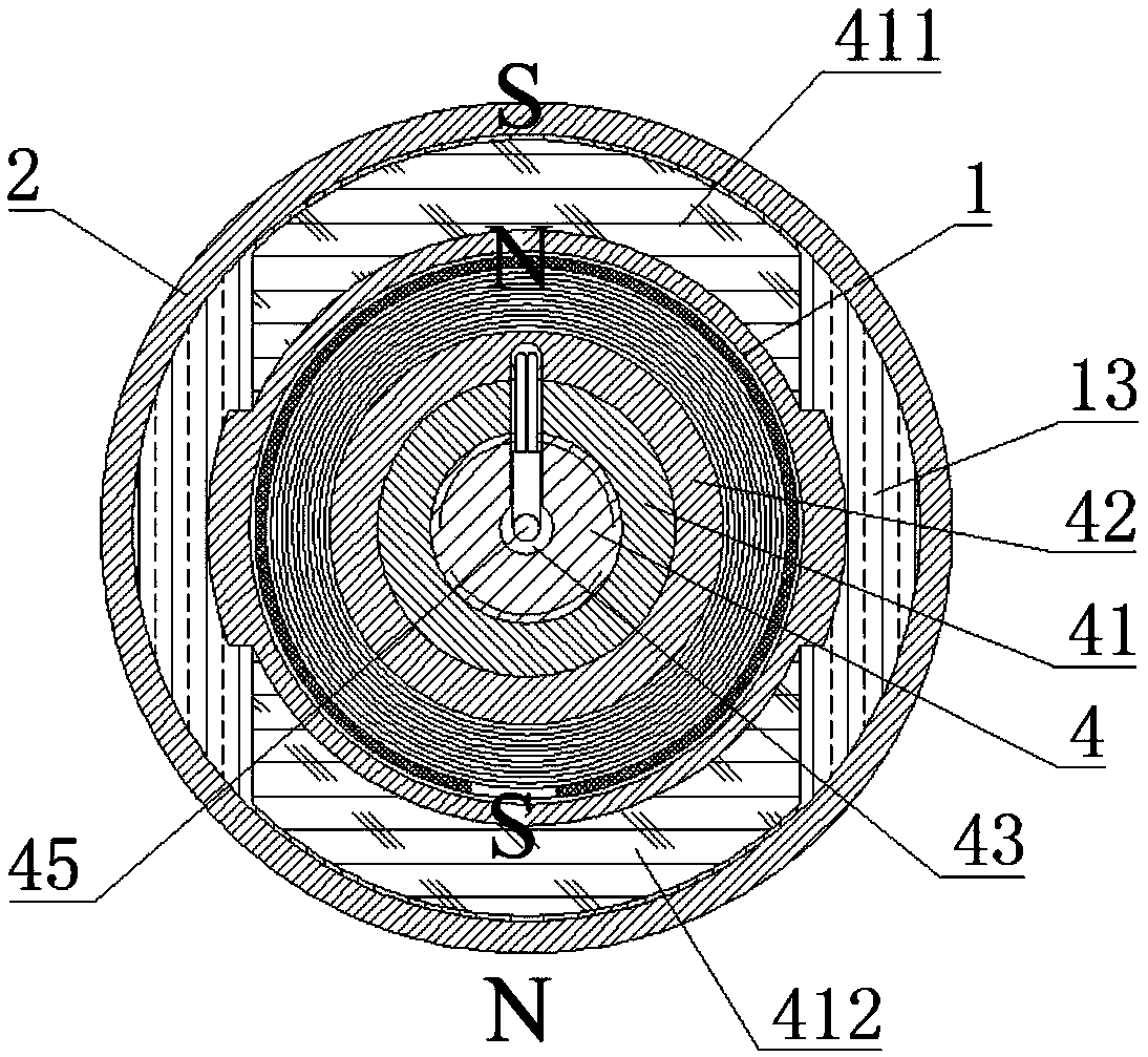
Vehicular shock absorber capable of generating electricity

A shock absorber and shock absorber body technology, which is applied in the direction of shock absorber, spring/shock absorber, shock absorber, etc., can solve the problems of unsatisfactory cruising range, inability to replenish energy in time, and inability to get large electric vehicles. The scope of promotion and other issues to achieve the effect of saving time and cost

Active Publication Date: 2019-03-01
GUANGZHOU OCEAN HYDRAULIC ELEMENTS CO LTD
View PDF7 Cites 7 Cited by
  • Summary
  • Abstract
  • Description
  • Claims
  • Application Information

AI Technical Summary

Problems solved by technology

In recent years, with the continuous development of science and technology, various types of electric vehicles have emerged one after another, but most of them are in an embarrassing situation due to unsatisfactory cruising range, incomplete charging facilities, long charging time and high battery replacement costs.
The most important problem is that due to the limitation of battery technology, the cruising range of electric vehicles is short, and the energy cannot be replenished in time during long-distance driving, which causes some users to worry about whether to buy electric vehicles. cannot be widely promoted
[0003] On the other hand, when the car is running, the wheel will vibrate due to the contact with the ground, so it is necessary to install a shock absorber to suppress the shock when the spring rebounds after absorbing the shock and the impact from the road surface, so as to improve the ride comfort of the vehicle, thereby improving the ride quality. However, the existing automobile shock absorbers use the damping effect of hydraulic oil to consume vibration energy, which cannot realize the recovery and reuse of vibration energy, and cannot convert this part of energy into energy for electric vehicles

Method used


Image

  • Vehicular shock absorber capable of generating electricity
  • Vehicular shock absorber capable of generating electricity

Examples


Embodiment Construction

[0021] The specific implementation manners of the present invention will be further described in detail below in conjunction with the accompanying drawings and embodiments. The following examples are used to illustrate the present invention, but are not intended to limit the scope of the present invention.

[0022] In the description of the present invention, it should be noted that the terms "center", "longitudinal", "transverse", "upper", "lower", "front", "rear", "left", "right", " The orientations or positional relationships indicated by "vertical", "horizontal", "top", "bottom", "inner", "outer", etc. are based on the orientation or positional relationships shown in the drawings, and are only for the convenience of describing the present invention and simplifying Describes, but does not indicate or imply that the device or element referred to must have a specific orientation, be constructed in a specific orientation, and operate in a specific orientation, and therefore sh...


PUM


Abstract

The invention relates to the field of vehicle energy recovery equipment, and particularly discloses a vehicular shock absorber capable of generating electricity. The vehicular shock absorber capable of generating the electricity comprises a shock absorber body, a piston rod and bearing springs; the shock absorber body comprises an inner cylinder tube and an outer cylinder tube, and an oil storagecavity chamber which is in intercommunication with an inner cavity of the inner cylinder tube is formed between the inner cylinder tube and the outer cylinder tube; and the two ends of the bearing springs are connected with the upper end of the piston rod and the outer cylinder tube correspondingly; and pistons slidably matched with the inner cylinder tube are connected to the bottom end of the piston rod, a coil is arranged in the pistons in a seal mode, two pieces of permanent magnets with relative magnetic poles are arranged on the opposite two sides of the oil storage cavity chamber correspondingly, and the coil is connected with a electrode cable. The shock absorber referred can make vehicles obtain the supplement of electric power energy in the process of moving under the condition that the energy and time costs are not additionally increased.

Description

technical field [0001] The invention relates to the technical field of vehicle energy recovery devices, in particular to a vehicle shock absorber capable of generating electricity. Background technique [0002] At present, the air pollution in cities is very serious. Automobile exhaust emission is the main cause of air pollution. The study of zero emission and less emission of automobiles has become a major issue to solve urban environmental protection problems. The development of electric vehicles is one of the effective measures to solve air pollution. In recent years, with the continuous development of science and technology, various types of electric vehicles emerge in an endless stream, but most of them are in an embarrassing situation due to unsatisfactory cruising range, incomplete charging facilities, long charging time and high battery replacement cost. The most important problem is that due to the limitation of battery technology, the cruising range of electric veh...

Claims


Application Information

Patent Timeline
Patent Type & Authority Applications(China)
IPC IPC(8): F16F9/16F16F9/32F16F13/00H02K35/04
CPCH02K35/04F16F9/16F16F9/3207F16F9/3214F16F9/3221F16F13/002F16F13/007B60G2300/60B60G13/14B60G15/06F16F9/3235
Inventor 王文平王绍伟
Owner GUANGZHOU OCEAN HYDRAULIC ELEMENTS CO LTD
Why Eureka
Try Eureka