
Plasma enhancement type microchip exploding foil initiator and preparation method

A plasma and enhanced technology, applied in blasting barrels, offensive equipment, weapon accessories, etc., can solve the problems of low precision, high manufacturing cost, and reduce the ignition energy of McEFI, and achieve high integration, reduce manufacturing cost, and enhance capabilities Effect

Inactive Publication Date: 2019-03-01
NANJING UNIV OF SCI & TECH
View PDF6 Cites 10 Cited by
  • Summary
  • Abstract
  • Description
  • Claims
  • Application Information

AI Technical Summary

Problems solved by technology

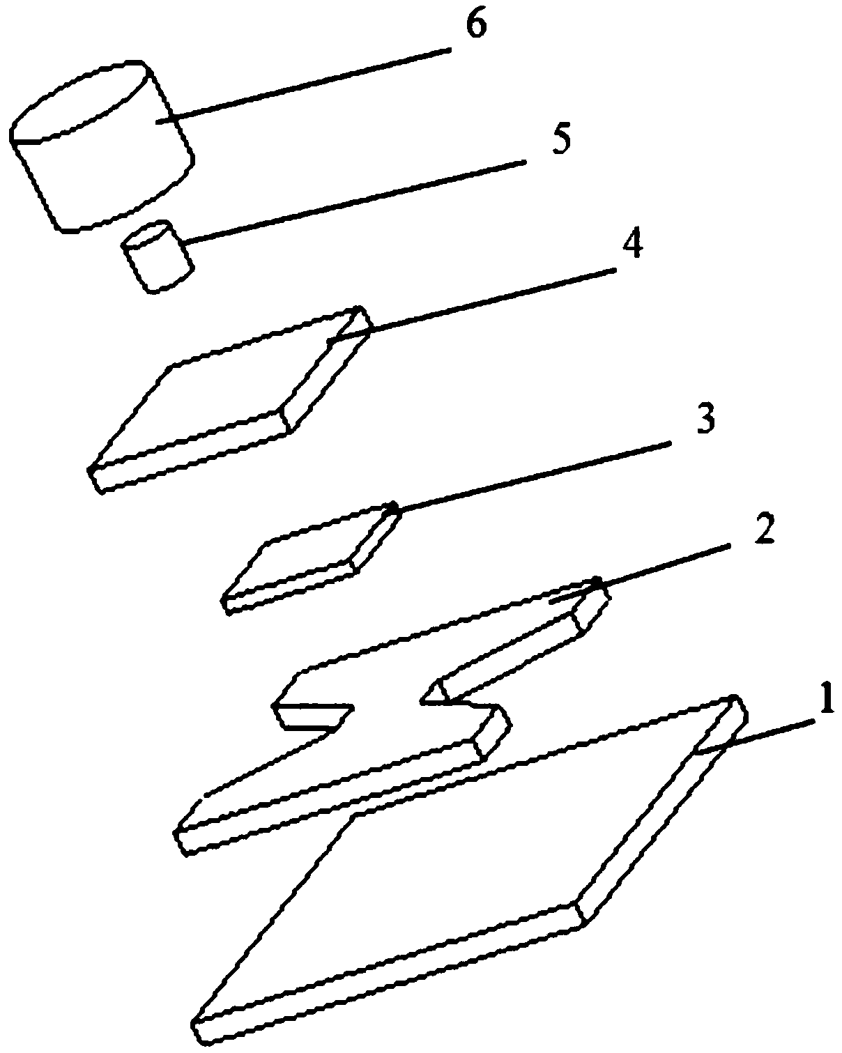
[0003] Exploding foil initiator (Exploding Foil Initiator, EFI) is also called shock foil detonator. It is usually composed of substrate, explosive bridge foil, flyer layer, accelerating chamber and agent. It is an extremely safe and reliable ignition and detonation device. Traditional EFI, each component is manually aligned and installed, resulting in low precision and high manufacturing cost. Using Micro Electro Mechanical System (MEMS) technology, integrated batch preparation of McEFI has become a new research trend
[0004] However, the ignition (ignition or detonation) energy of the current McEFI is relatively high, and the energy provided by the weapon system (such as solid rocket motor or missile fuze, etc.) is extremely limited, so how to reduce the ignition energy of McEFI, based on McEFI Preparation of Low Energy Exploding Foil Initiator (LEEFI) has become a current and future research hotspot

Method used


Image

  • Plasma enhancement type microchip exploding foil initiator and preparation method
  • Plasma enhancement type microchip exploding foil initiator and preparation method
  • Plasma enhancement type microchip exploding foil initiator and preparation method

Examples


Embodiment example

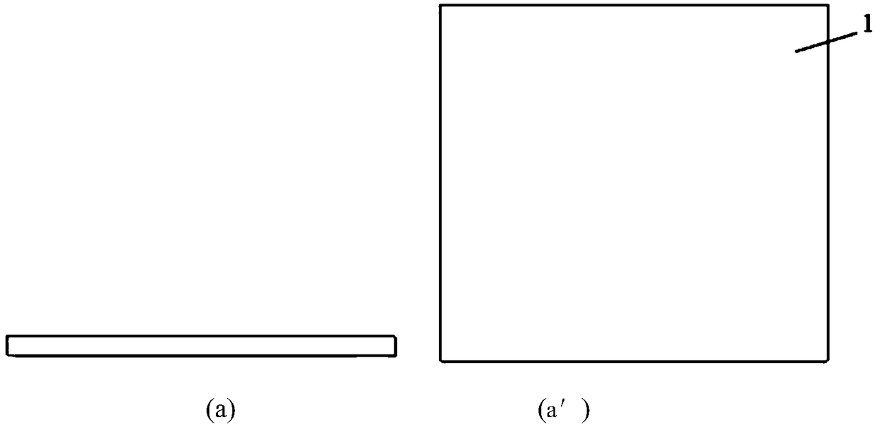
[0050] In this implementation case, an ignition circuit is designed on the basis of preparing McEFI, combined with image 3 and Figure 4 , including the following steps (Note: image 3 The left and right figures in the figure are the front view and top view of the preparation process respectively):

[0051] first step, see image 3 (a) and (a'), for 50.8mm (length) × 50.8mm (width) × 0.635mm (height) Al 2 o 3 The surface of the ceramic substrate 1 is cleaned.

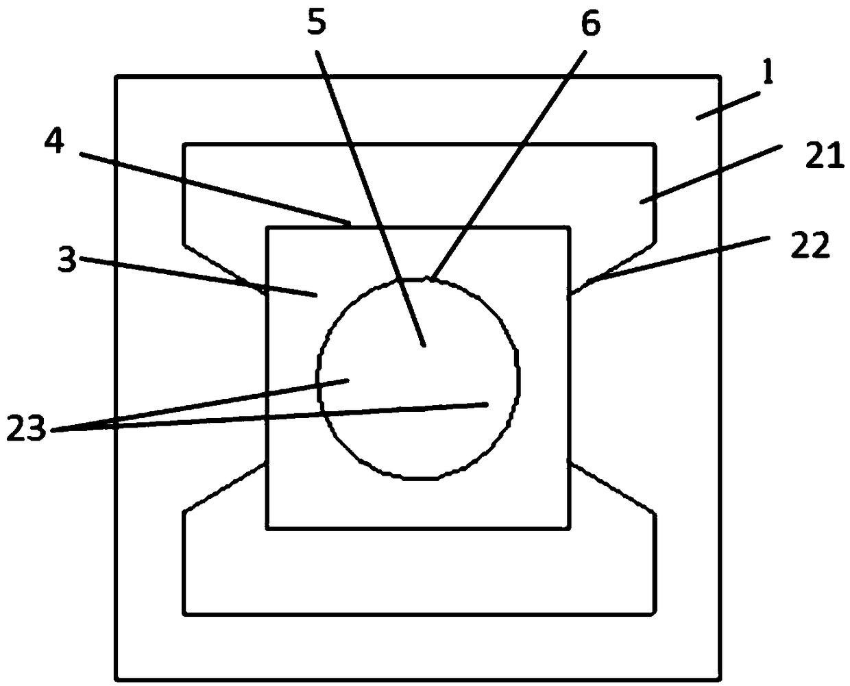
[0052] The second step, see image 3 (b) and (b′), using magnetron sputtering and wet etching process on Al 2 o 3 A Cu metal layer is deposited on the surface of the ceramic substrate 1 to form pads 21 , transition regions 22 and metal bridge foils 23 . Relevant dimensions are: the width of pad 21 is 5mm-10mm; the distance from metal bridge foil 23 to pad 21 is 5mm-6mm; the size of bridge foil is 0.4mm (length)×0.4mm (width)×3.6μm (height); The disc 21 is connected to the middle of the metal layer by a transit...


PUM

PropertyMeasurementUnit
Thicknessaaaaaaaaaa
Thicknessaaaaaaaaaa

Abstract

The invention relates to the technical field of minitype low-energy ignition and initiation, in particular to a plasma enhancement type microchip exploding foil initiator and a preparation method. Theinitiator comprises a substrate, a metal / low-melting-point polymer film layer, a tensile polymer flyer layer, an accelerating chamber and a reagent, wherein the metal / low-melting-point polymer film layer includes a metal layer and a low-melting-point polymer layer; the mental layer is arranged on the substrate and includes a bonding pad, a transition zone and bridge foils; and the low-melting-point polymer layer is arranged on the metal layer. The tensile polymer flyer layer is arranged on the metal / low-melting-point polymer film layer. According to the plasma enhancement type microchip exploding foil initiator and the preparation method, by using the metal / polymer layer, polymers can be activated to generate a large amount of steam and plasmas on the basis of an electric explosion of thebridge foils, and the capacities of the bridge foils to shear and drive the flyer are enhanced, and the ignition energy of an McEFI is reduced; adopting a micro-electromechanical system technology toprepare the microchip exploding foil initiator can realize mass production and reduce the preparation cost, and the obtained initiator has a high integration level and a small size.

Description

technical field [0001] The invention relates to the technical field of miniature low-energy ignition and detonation, in particular to a plasma-enhanced microchip explosion foil detonator and a preparation method. Background technique [0002] Low-energy ignition and detonation is the development trend of ignition and detonation in weapon systems. [0003] Exploding foil initiator (Exploding Foil Initiator, EFI) is also called shock foil detonator. It is usually composed of substrate, explosive bridge foil, flyer layer, accelerating chamber and agent. It is an extremely safe and reliable ignition and detonation device. Traditional For EFI, each component is manually aligned and installed, resulting in low precision and high manufacturing cost. Using Micro Electro Mechanical System (MEMS) technology, integrated batch preparation of McEFI has become a new research trend. [0004] However, the ignition (ignition or detonation) energy of the current McEFI is relatively high, and...

Claims


Application Information

Patent Timeline
IPC IPC(8): F42B3/10F42B3/195
CPCF42B3/10F42B3/195
Inventor 朱朋杨智徐聪张秋汪柯刘鹏沈瑞琪
Owner NANJING UNIV OF SCI & TECH
Features
  • Generate Ideas
  • Intellectual Property
  • Life Sciences
  • Materials
  • Tech Scout
  • Unparalleled Data Quality
  • Higher Quality Content
  • 60% Fewer Hallucinations
Learn More