Testing system of robot reducer

A test system and reducer technology, applied in the field of robots, can solve problems such as reducing test work efficiency, and achieve the effects of strong practicability, high test accuracy and high utilization rate

Inactive Publication Date: 2019-03-01
WUHU CITY YUEZE ROBOT TECH CO LTD
View PDF0 Cites 4 Cited by
  • Summary
  • Abstract
  • Description
  • Claims
  • Application Information

AI Technical Summary

Problems solved by technology

[0004] Aiming at the deficiencies of the prior art, the present invention provides a test system for a robot reducer, which sol

Method used


Image

  • Testing system of robot reducer
  • Testing system of robot reducer
  • Testing system of robot reducer

Examples


Embodiment Construction

[0022] The following will clearly and completely describe the technical solutions in the embodiments of the present invention with reference to the accompanying drawings in the embodiments of the present invention. Obviously, the described embodiments are only some, not all, embodiments of the present invention. Based on the embodiments of the present invention, all other embodiments obtained by persons of ordinary skill in the art without making creative efforts belong to the protection scope of the present invention.

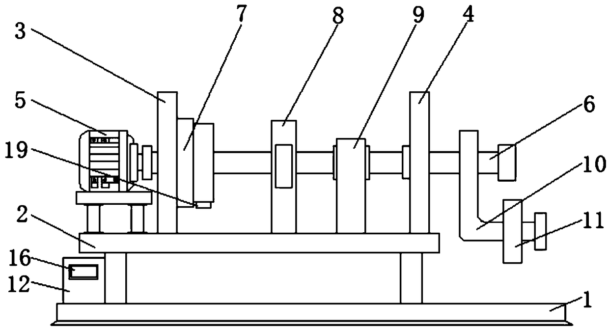
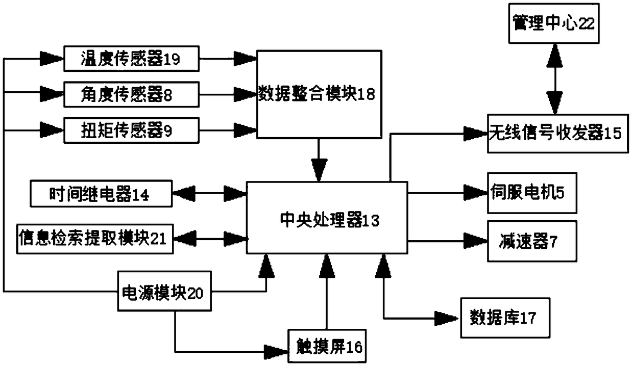
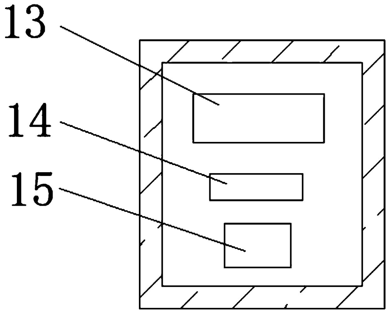
[0023] see Figure 1-3 , the present invention provides a technical solution: a test system for a robot reducer, including a bottom plate 1, a rectangular box 12 is fixedly connected to one side of the top of the bottom plate 1, and the back of the inner wall of the rectangular box 12 is fixedly connected with Central processing unit 13, time relay 14 and wireless signal transceiver 15, central processing unit 13 and wireless signal transceiver 15 realize two-...


PUM


Abstract

The invention discloses a testing system of a robot reducer. The testing system comprises a base plate. The top of the base plate is fixedly connected with a supporting platform through a supporting frame. Two sides of top of the supporting platform are fixedly connected with a vertical plate and a separator plate successively from left to right. The top of the supporting plate is arranged at oneside of the vertical plate, and furthermore is fixedly connected with a servo motor through a supporting base. One end of the output shaft of the servo motor is fixedly connected with a rotating rod through a shaft coupling. One end of the rotating rod successively penetrates through the vertical plate and the separator plate and extends to one side of the separator plate. The surface of the rotating rod is movably connected with a reducer. One side of the reducer is fixedly connected with the other side of the vertical plate. The invention relates to the field of robot technology. The testingsystem of the robot reducer can realize a series of integrated testing on the temperature change, the angle value and the torque value of the reducer. The testing system of the robot reducer has advantages of high testing precision of an integral testing mechanism, high utilization rate, high practicability, and benefit for personnel.

Description

technical field [0001] The invention relates to the technical field of robots, in particular to a test system for a robot reducer. Background technique [0002] The reducer is an independent component composed of gear transmission, worm drive and worm drive enclosed in a rigid shell. It is often used as a reduction transmission device between the prime mover and the working machine. It plays the role of matching speed and transmitting torque. It is widely used in modern machinery. The reducer is generally used for low-speed and high-torque transmission equipment. The motor, internal combustion engine or other high-speed power is passed through the gear on the input shaft of the reducer To achieve the purpose of deceleration, the ordinary reducer will also have several pairs of gears with the same principle to achieve the ideal deceleration effect. The ratio of the number of teeth of the large and small gears is the transmission ratio. The reducer is a mechanical transmission...

Claims


Application Information

Patent Timeline
IPC IPC(8): G01M13/025
CPCG01M13/025
Inventor 吴丹阳黄浩
Owner WUHU CITY YUEZE ROBOT TECH CO LTD
Why Eureka
Try Eureka