Data transmission method and device for network-on-chip NOC and electronic equipment

A data transmission method and a network-on-chip technology are applied in the field of data transmission methods of devices, electronic equipment, and network-on-chip NOCs, and can solve the problems of high overhead, low transmission efficiency, and high power consumption, and achieve reduced power consumption and flexible routing. , the effect of reducing overhead

Active Publication Date: 2019-03-01
LYNXI TECH CO LTD
View PDF3 Cites 12 Cited by
  • Summary
  • Abstract
  • Description
  • Claims
  • Application Information

AI Technical Summary

Problems solved by technology

[0005] In view of this, the present invention provides a data transmission method, device and electronic equipment for the network on chip NOC, which is used to solve the problem of huge overhead in the prior art when many-core chips use NOC for communication between cores , high power consumption and low transmission efficiency

Method used


Image

  • Data transmission method and device for network-on-chip NOC and electronic equipment
  • Data transmission method and device for network-on-chip NOC and electronic equipment
  • Data transmission method and device for network-on-chip NOC and electronic equipment

Examples


specific Embodiment 1

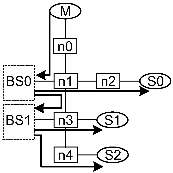
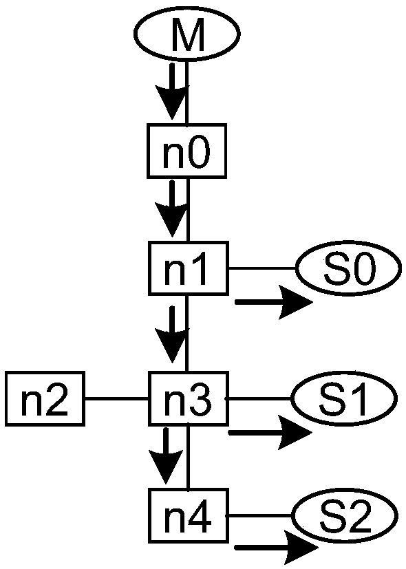
[0060] Assuming that the propagation direction of the data packet is a fixed one-way propagation, the specific sending flow diagram of the data packet is as follows: image 3 As shown, the master data sending unit M multicasts the data packet to the slave data receiving units S0, S1 and S2, n0 receives the data packet sent by M, sends the data packet to n1, and n1 sends the data packet to S0 and S2 n3, n3 sends the data packet to S1 and n4, n4 sends the data packet to S2, the specific processing flow is as follows Figure 4 Shown:

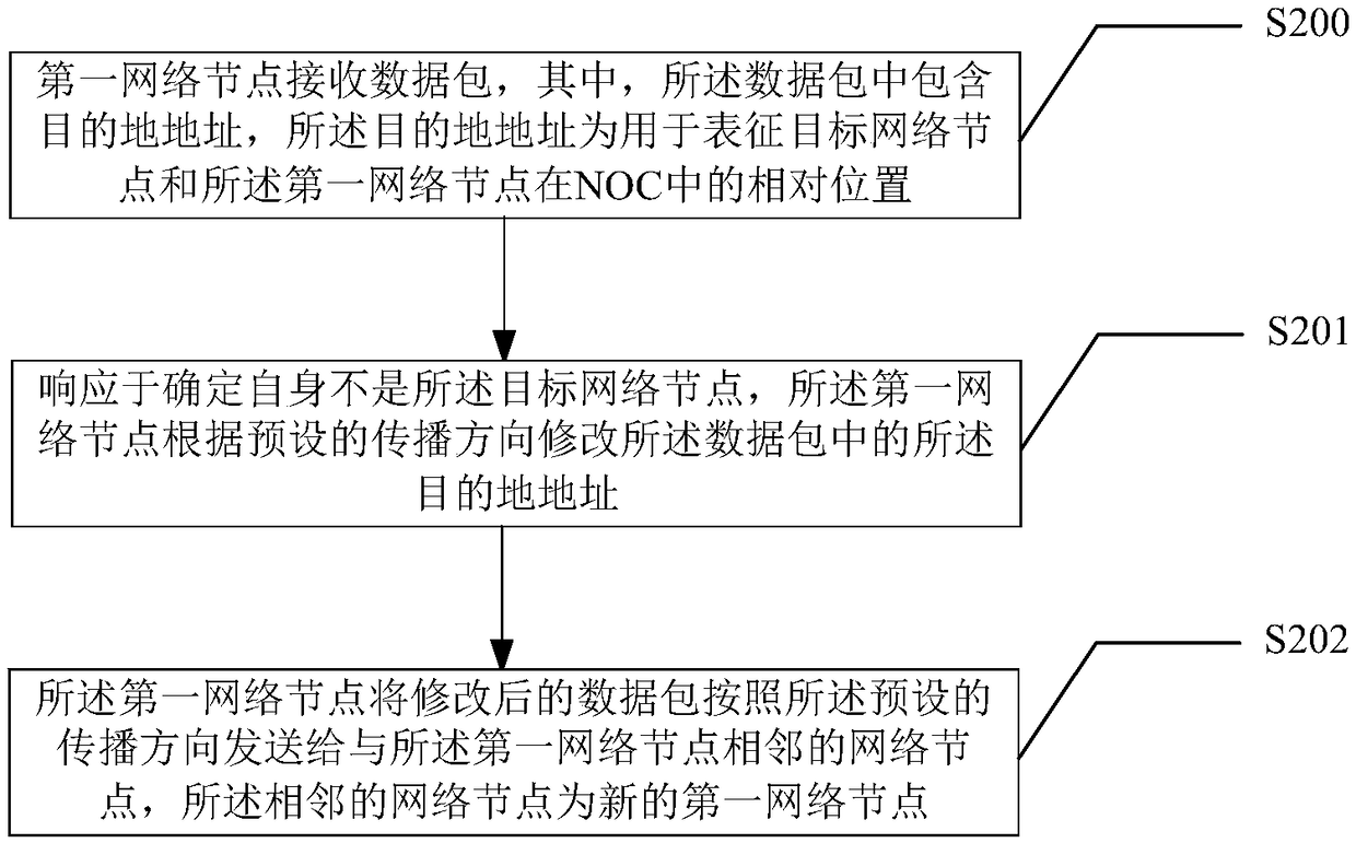
[0061] Step S400, the network node n0 receives the first data packet sent by M, and determines that the destination address in the first data packet is (1).

[0062] Step S401, determining that the preset propagation direction of the network node n0 is fixed unidirectional propagation.

[0063] Step S402, the network node n0 modifies the destination address in the first data packet to (0), and determines the modified data packet with the address ...

specific Embodiment 2

[0073] Assume that core C0 multicasts data to cores C4, C5, and C7. The specific schematic diagram is as follows Figure 5 As shown, wherein, the one that needs multicast data can be a processing unit circuit or a main data sending unit M, and the propagation direction is first the X axis and then the Y axis, and the specific processing flow is as follows Image 6 shown.

[0074] Step S600, the network node n0 receives the first data packet sent by the core C0, and determines that the destination address in the first data packet is (1, 1).

[0075] Step S601 , according to the destination address, determine that it is not the target network node, and determine that the preset propagation direction of the network node n0 is the first X axis.

[0076] Step S602, the network node n0 modifies the destination address in the first data packet to (0, 1), and determines the modified data packet with the address of (0, 1) as the second data packet.

[0077] Step S603, the network nod...


PUM


Abstract

The invention provides a data transmission method and device for a network-on-chip NOC and electronic equipment, and is used for solving the problems that in the prior art, when a many-core chip adopts the NOC to carry out communication between cores, the expenditure is huge, the power consumption is high, and the transmission efficiency is low. The method comprises the steps that a first networknode receives a data packet, and the data packet comprises a destination address which is used for representing the relative positions of a target network node and the first network node in NOC; In response to determining that the first network node is not the target network node, the first network node modifies the destination address in the data packet according to a preset propagation direction; and the first network node sends the modified data packet to a network node adjacent to the first network node according to the preset propagation direction, wherein the adjacent network node is a new first network node.

Description

technical field [0001] The invention relates to the field of communication technology, in particular to a data transmission method, device and electronic equipment for a network on chip (NOC). Background technique [0002] With the development of artificial intelligence technology, users have higher and higher requirements for chip processing capabilities. Since the processing capability of single-core chips is limited, many-core chips are used more and more widely. In the design of many-core chips, a network on chip (Networks on Chip, NOC) is used to implement communication between cores. Therefore, the performance of the NOC is the key to the performance of many-core chips. [0003] In the prior art, many-core chips use NOC to communicate between cores. For example, the master data sending unit (Master, M) and multiple slave data receiving units (Slave, S) are the cores that need to communicate. , when M multicasts the data packet to multiple Ss, the specific method is as...

Claims


Application Information

Patent Timeline
Patent Type & Authority Applications(China)
IPC IPC(8): G06F9/54
CPCG06F9/542G06F9/543
Inventor 冯杰
Owner LYNXI TECH CO LTD
Why Eureka
Try Eureka