A design method of a turbofan ramjet combined engine with an external culvert and a built-in rocket

A technology of turbofan engine and design method, which is applied in the direction of combined engine, ramjet engine, mechanical equipment, etc. It can solve the problem that it is difficult to meet the thrust demand of aircraft, the working Mach number of the ramjet engine cannot be lowered, and the working Mach number of the turbine engine cannot be increased, etc. problems, to achieve the effect of improving overall performance, moderate technical difficulty, and simple and reliable structure

Active Publication Date: 2019-03-01
XIAMEN UNIV
View PDF11 Cites 4 Cited by
  • Summary
  • Abstract
  • Description
  • Claims
  • Application Information

AI Technical Summary

Problems solved by technology

[0003] At present, the working Mach number of the turbine engine is mainly Mach 0~2, and the working Mach number of the ramjet engine is Ma3~6 + , in the range of Mach 2 to 3, the TBCC power system has the problem that the working Mach number of the turbine engine cannot be increased, and the working Mach number of the ramjet engine cannot be lowered. During the mode conversion process, the thrust of the combined engine cannot meet the thrust demand of the aircraft, and it is insurmountable. Thrust gap”; in addition, the existing turbine engines mainly adopt the structural form of the turbofan engine, and the afterburner of the turbofan engine is essentially a sub-combustion chamber

Method used


Image

  • A design method of a turbofan ramjet combined engine with an external culvert and a built-in rocket
  • A design method of a turbofan ramjet combined engine with an external culvert and a built-in rocket
  • A design method of a turbofan ramjet combined engine with an external culvert and a built-in rocket

Examples


Embodiment Construction

[0040] In order to make the technical problems, technical solutions and beneficial effects to be solved by the present invention clearer, the present invention will be further described in detail below in conjunction with the accompanying drawings and embodiments.

[0041] A design method for a turbofan ramjet engine with a built-in rocket, comprising the following steps:

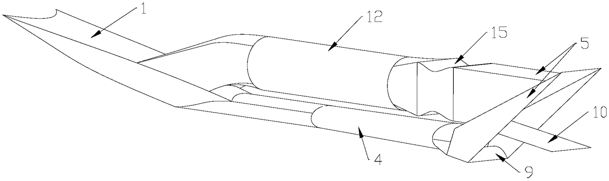
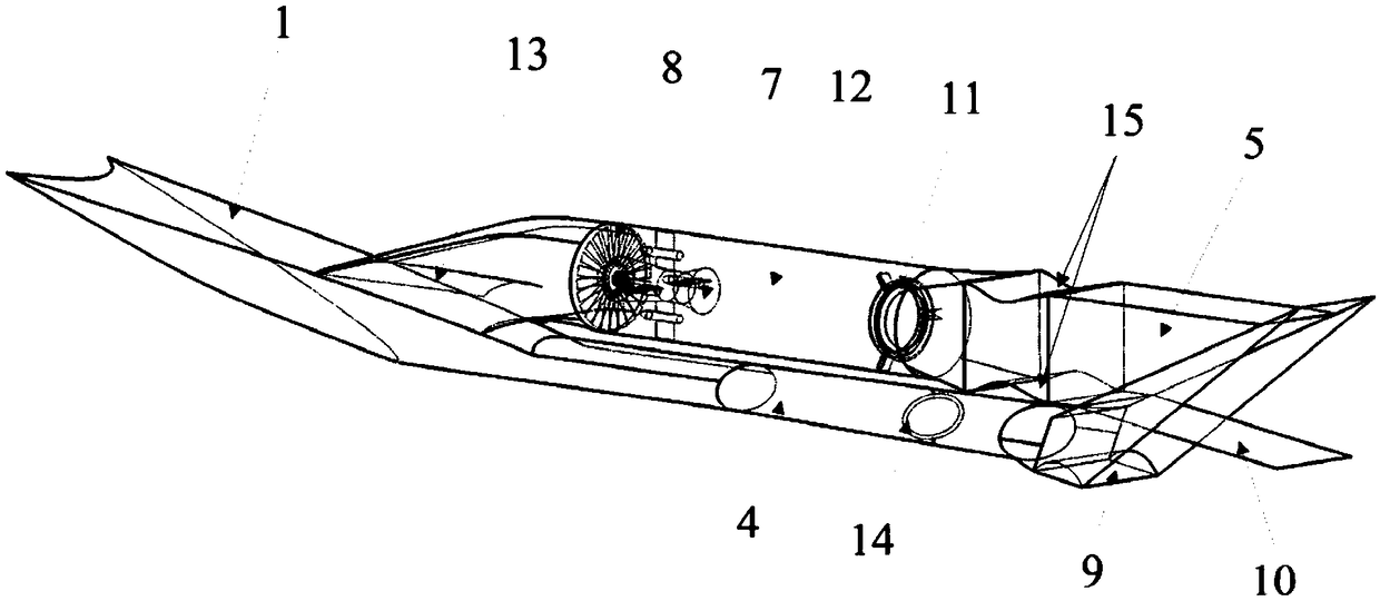
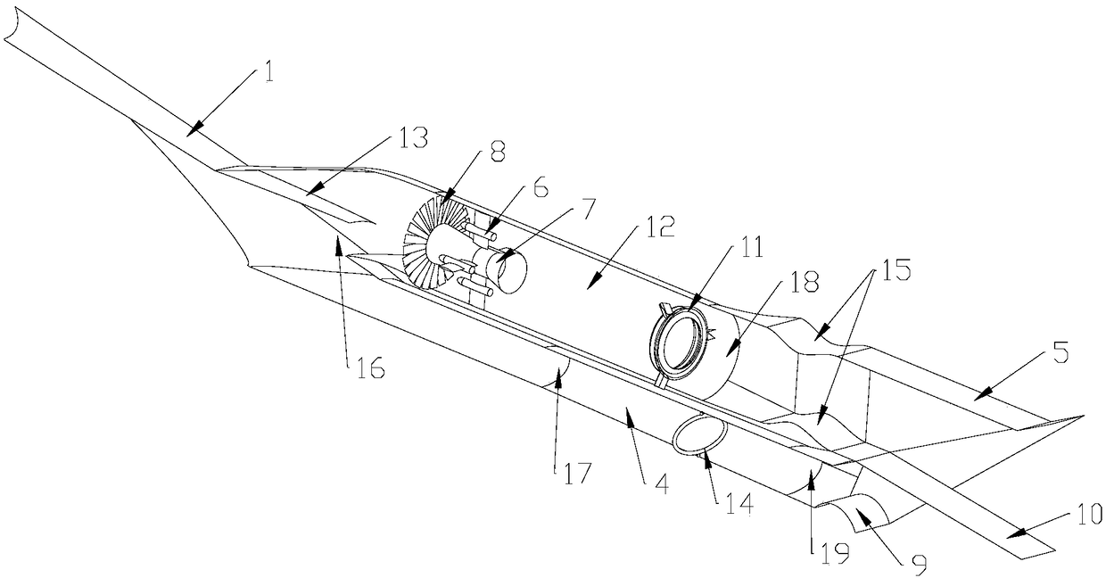
[0042]1) Formulate the overall performance requirements of the engine according to the flight mission, design the basic flow field of the inlet based on the overall performance requirements, and then obtain the three-dimensional inward turning inlet by performing streamline tracing in the basic flow field;

[0043] 2) Obtain the inlet and outlet parameters of the scram chamber according to the overall performance of the engine, and design the scram chamber at the outlet of the three-dimensional internal turning inlet described in step 1);

[0044] 3) Based on step 2) SFC combustion chamber parameters and en...


PUM


Abstract

A design method of a turbofan ramjet combined engine with an external culvert and a built-in rocket belongs to the field of combined engines, and comprises the following steps: firstly, formulating overall performance requirements of the engine, designing a basic flow field of an air inlet channel, and then carrying out streamline tracking to obtain a three-dimensional internal rotation air inletchannel; Inlet and outlet parameters of the scramjet combustion chamber are obtained according to the overall performance of the engine, and the scramjet combustion chamber is designed at an outlet ofthe three-dimensional internal rotation air inlet channel; Designing an exhaust nozzle with an adjustable geometric area at an outlet of the scramjet chamber on the basis of parameters of the scramjet chamber and the thrust requirement of the engine at the Ma4.5-6 + stage; Selecting a turbofan engine on the basis of engine performance requirements at stages Ma0-2, and arranging turbofans at openings in the upper wall surfaces of the three-dimensional inward rotating air inlet channels; A sub-combustion combination channel and a turbofan engine; A rocket engine is arranged in an outer culvertchannel of the turbofan engine; based on the thrust requirement of an engine in the Ma0-5 state, and in combination with the performance parameters of a turbofan engine in the Ma0-2 state and a rocketengine in the Ma2-3 state, a sub-combustion chamber capable of switching working modes is designed behind the turbofan engine.

Description

technical field [0001] The invention relates to the field of combined engines, in particular to a design method of a turbofan ramjet combined engine with built-in rockets. Background technique [0002] Hypersonic flight is considered to be the third revolution after propellers and jet propulsion. All major military powers in the world, led by the United States, attach great importance to the research of hypersonic aircraft technology. At present, the academic research frontiers of hypersonic vehicles are shifting from the development of scramjet engines to the research of combined power systems capable of horizontal take-off and autonomous acceleration to hypersonic speeds, among which the development of turbine-based combined cycle engines is the most important focus. Turbine-based combined cycle engine (TBCC) refers to a power plant composed of a turbine engine and other types of engines. It is one of the key power systems for hypersonic vehicles to achieve autonomous acc...

Claims


Application Information

Patent Timeline
Patent Type & Authority Applications(China)
IPC IPC(8): G06F17/50F02K7/18
CPCF02K7/18G06F30/15
Inventor 尤延铖孙伟强朱剑锋
Owner XIAMEN UNIV
Why Eureka
Try Eureka