Infrared polarization image fusion method based on multi-feature and feature difference driving

A feature difference and infrared polarization technology, applied in image enhancement, image analysis, image data processing, etc., can solve the problems of ineffective description of image features, information redundancy, etc.

Active Publication Date: 2019-03-01
HUNAN VISION SPLEND PHOTOELECTRIC TECH
View PDF6 Cites 3 Cited by
  • Summary
  • Abstract
  • Description
  • Claims
  • Application Information

AI Technical Summary

Problems solved by technology

[0008] Aiming at the problem that the image fusion algorithm that only considers a single difference feature in the prior art cannot effectively describe all uncertain and randomly changing image features in the image, the purpose of the present invention is to provide an image fusion algorithm based on multiple features and features The difference-driven infrared polarization image fusion method combines multiple polarization images of infrared polarization images, and multiple polarization quantities include image Q, image U, image V, total light intensity image I, polarization degree image P and polarization angle image R, It makes the fused image scene richer, and at the same time integrates multiple uncertain and randomly changing image features, so that the fusion process takes into account multiple features of the image, enhances the edge detail information of the image, improves the contrast of the image, and improves the fusion result. It is helpful to identify camouflage targets, and at the same time, in the process of image fusion, the problem of information redundancy between each polarization value is effectively solved by obtaining the unique parts of each polarization image

Method used


Image

  • Infrared polarization image fusion method based on multi-feature and feature difference driving
  • Infrared polarization image fusion method based on multi-feature and feature difference driving
  • Infrared polarization image fusion method based on multi-feature and feature difference driving

Examples


Embodiment Construction

[0119] In order to facilitate the implementation of the present invention, further description will be given below in conjunction with specific examples.

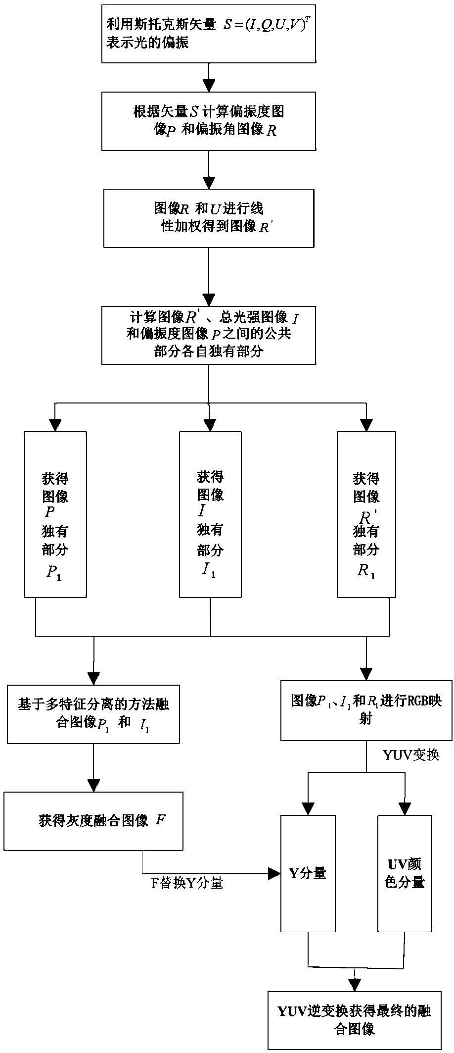
[0120] Such as figure 1 A method of infrared polarization image fusion driven by multi-features and feature differences is shown, which specifically includes the following steps:

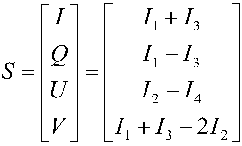
[0121] S1. Utilize the Stokes vector to represent the polarization of light, i.e. S=(I, Q, U, V), and calculate the degree of polarization image P and the polarization angle image R according to the S vector:

[0122] In actual polarization, the phase retarder is often not used, and the Stokes parameter can be obtained only by rotating the linear polarizer. Therefore, the polarization degree image P and polarization angle image R of polarized light can be expressed as:

[0123]

[0124] S2. Linearly weight the polarization angle images R and U to obtain the image R':

[0125] R'=(R+U) / 2.

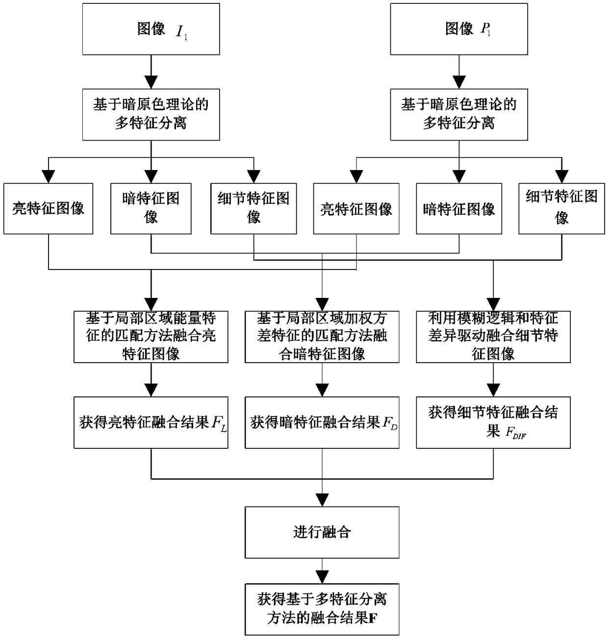
[0126] S3. The calculation image R', the total lig...


PUM


Abstract

The invention provides an infrared polarization image fusion method based on multi-feature and feature difference driving, which comprises the following steps: using a Stokes vector to represent the polarization of light, calculating a polarization degree image P and a polarization angle image R; linearly weighting the polarization angle images R and U to obtain an image R '; Between that computerimages R ', I, and P, the respective unique part of the common part is remove, denoted as R1, I1, and P1; the images P1, I1 and R1 are mapped to R channel, G channel and B channel in RGB space to obtain RGB image. The RGB image is converted to YUV image and the luminance component Y is extracted. The image I1 and P1 are fused by a method based on multi-feature separation to obtain F; F is substituted for Y to obtain the substituted YUV image, and the substituted YUV image is inversely transformed to obtain RGB image, that is, the result of polarization image fusion. Multiple polarization images of infrared polarization images are fused, which makes the fused image scene richer and helps to identify the camouflage targets. The invention is applied to the field of computer vision.

Description

technical field [0001] The invention relates to the field of computer vision, in particular to an infrared polarization image fusion method based on multi-feature and feature difference driving. Background technique [0002] Today, with the vigorous development of infrared imaging detection technology in military, medical, security and earth observation applications, traditional infrared detection technology is somewhat powerless under the upgrade of precision, complex environment and camouflage technology. The traditional infrared imaging system mainly images the infrared radiation intensity of the scene, which is mainly related to the temperature and emissivity of the scene. When a noise source with the same temperature is placed around the target, the existing thermal imaging camera cannot identify the target, and infrared imaging technology faces serious limitations and challenges. [0003] Compared with traditional infrared imaging, the polarization imaging of light ca...

Claims


Application Information

Patent Timeline
Patent Type & Authority Applications(China)
IPC IPC(8): G06T5/50
CPCG06T5/50G06T2207/10024G06T2207/10048G06T2207/20192G06T2207/20221
Inventor 冉骏宋斌陈蓉
Owner HUNAN VISION SPLEND PHOTOELECTRIC TECH
Why Eureka
Try Eureka