Display panel and display device

A display panel and display module technology, applied in the direction of identification devices, instruments, etc., can solve problems such as unfavorable ultra-thin

Active Publication Date: 2021-11-26
K TRONICS (SUZHOU) TECH CO LTD +1
View PDF8 Cites 0 Cited by
  • Summary
  • Abstract
  • Description
  • Claims
  • Application Information

AI Technical Summary

Problems solved by technology

[0006] The object of the present invention is to overcome the disadvantages of the above-mentioned prior art that are not conducive to realizing ultra-thinning, and provide a display panel capable of achieving ultra-thinning and a display device equipped with the display panel

Method used


Image

  • Display panel and display device
  • Display panel and display device
  • Display panel and display device

Examples


Embodiment approach 1

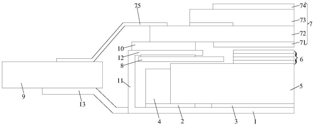
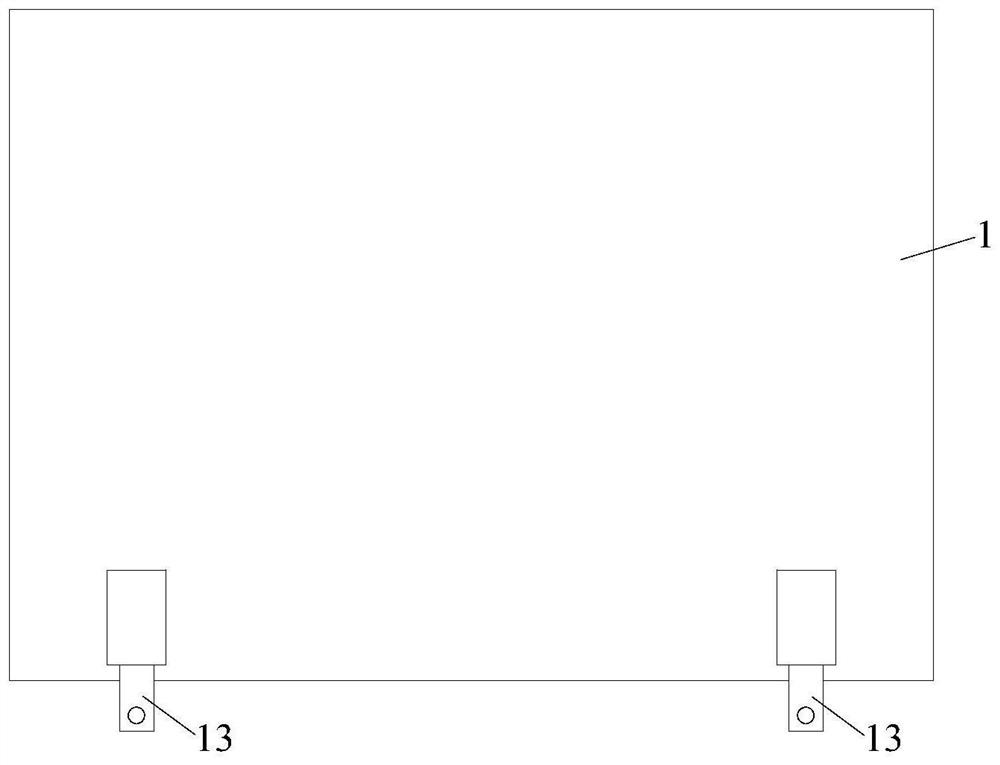
[0065] refer to Image 6 Shown is a schematic structural diagram of an embodiment of the display panel of the present invention; the display panel may include a backlight module and a display module 7 . refer to Figure 7 The schematic diagram of the structure of the backlight module shown, the backlight module can include a backplane 1, a circuit layer 2 and a white reflective sheet 3 are arranged on the backplane 1, and the circuit layer 2 forms a driving circuit for the light source 4; on the circuit layer 2 A light source 4 is provided on the side away from the backboard 1, and a light guide plate 5 is provided on the side of the white reflective sheet 3 away from the backboard 1, and the light guide plate 5 is located on the light emitting side of the light source 4; One side of the optical film layer 6 is provided, and the number of layers and the thickness of the optical film layer 6 can be set according to different layers and thicknesses. refer to Figure 8 The sch...

Embodiment approach 2

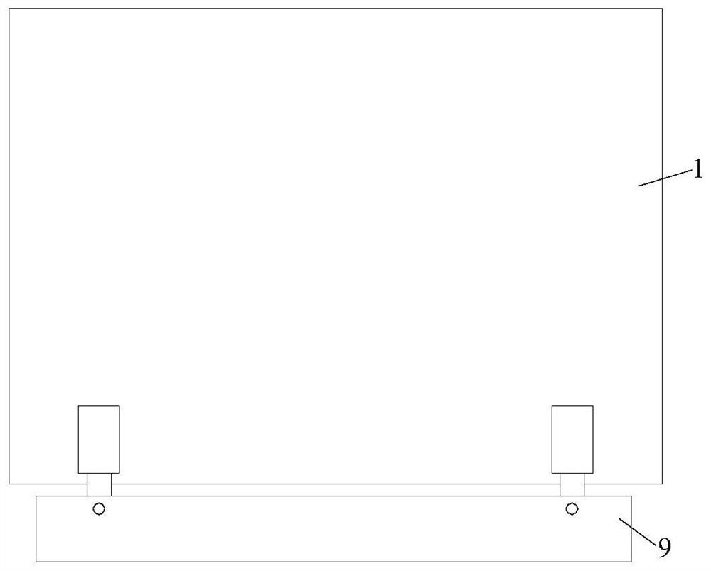
[0071] The structure of this exemplary embodiment is basically the same as that of the first exemplary embodiment, and the main difference lies in the structure of the backplane 1 . refer to Figure 11 As shown in the structural diagram of another embodiment of the display panel, since the circuit board 9 is relatively thin, the backplane 1 can be bent so that the circuit board 9 can support the display module 7 . The backplane 1 may include a backplane body 14 , a first bending structure 15 and a second bending structure 16 . The backplane body 14 is arranged in a flat shape, and is arranged under the white reflective sheet and the circuit layer 2 . The first bending structure 15 is connected to the backplane body 14 and extends toward a side close to the display module 7 . The second bending structure 16 is connected to the first bending structure 15 and extends in the same direction as the backplane body 14. The circuit board 9 is arranged on the second bending structure ...

Embodiment approach 3

[0073] The structure of this exemplary embodiment is basically the same as that of the first exemplary embodiment, and the main difference lies in the structure of the backplane 1 . refer to Figure 12 In the schematic structural diagram of another embodiment of the display panel shown, since the circuit board 9 is relatively thick, the backplane 1 can be bent so that the circuit board 9 can support the display module 7 . The backplane 1 may include a backplane body 14 , a first bending structure 15 and a second bending structure 16 . The backplane body 14 is arranged in a flat shape, and is arranged under the white reflective sheet and the circuit layer 2 . The first bending structure 15 is connected to the back panel body 14 and extends to a side away from the display module 7 . The second bending structure 16 is connected to the first bending structure 15 and extends in the same direction as the backplane body 14. The circuit board 9 is arranged on the second bending stru...


PUM


Abstract

The present invention relates to the field of display technology, and proposes a display panel. The display panel includes a backplane, a circuit board, and a display module; the circuit board is connected to the entire surface of the backplane; Enable the circuit board to support the display module. The entire surface of the circuit board is connected to the backplane, avoiding the use of brackets in the prior art. The backplane has a large area and high strength, and will not be warped due to vibration or collision, so that it will not cause damage to the backplane The circuit board exceeds the upper surface of the display panel, affecting the overall thickness of the display panel; the display module is arranged on the side of the circuit board away from the back plate, so that the circuit board can support the display module. By supporting the display module through the circuit board, it is not necessary to specially arrange a structure for supporting the display module, which is beneficial to the ultra-thinning of the display panel.

Description

technical field [0001] The present invention relates to the field of display technology, in particular to a display panel and a display device installed with the display panel. Background technique [0002] In the field of display, the thinning and lightening of display devices is a development trend, and one of the directions is to use ultra-thin display panels. [0003] At present, the backplane in the display panel not only forms the support of the display module, but also forms a bracket to connect and support the circuit board. As a result, the bracket for fixing the circuit board has a small area and insufficient rigidity. Warping due to collisions and other reasons causes the circuit board to exceed the upper surface of the display panel, affecting the overall thickness of the display panel; the current structure of the backplane is not conducive to the ultra-thinning of the display panel. [0004] Therefore, it is necessary to study a new display panel and a display...

Claims


Application Information

Patent Timeline
Patent Type & Authority Patents(China)
IPC IPC(8): G09F9/30
CPCG09F9/301
Inventor 王致中
Owner K TRONICS (SUZHOU) TECH CO LTD
Why Eureka
Try Eureka