
Tight arrangement wire spring socket and processing method

A wire spring jack and processing method technology, which is applied in the manufacturing of contacts, electrical components, coupling devices, etc., can solve the problems of low reliability, large size of the wire spring jack, and inability to better meet the transmission of micro-current.

Inactive Publication Date: 2019-03-01
绵阳市华永盛科技有限公司
View PDF10 Cites 3 Cited by
  • Summary
  • Abstract
  • Description
  • Claims
  • Application Information

AI Technical Summary

Problems solved by technology

[0007] The technical problem to be solved by the present invention is: the size of the wire spring socket of the existing micro connector is relatively large, the reliability is not high, and it cannot better meet the needs of micro current transmission

Method used


Image

  • Tight arrangement wire spring socket and processing method
  • Tight arrangement wire spring socket and processing method
  • Tight arrangement wire spring socket and processing method

Examples


Embodiment 1

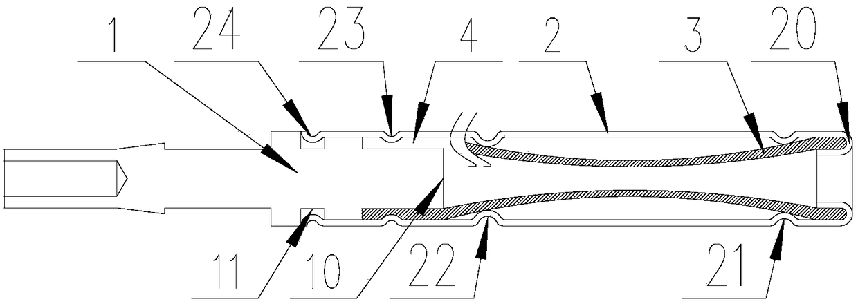
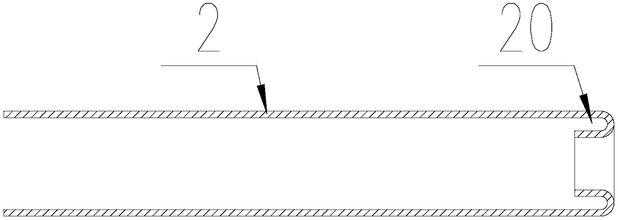
[0045] Such as Figure 1-Figure 3 As shown, a close-packed wire spring socket, a close-packed wire spring socket, includes a front cover 2, a rear cover 1 and a wire spring wire 3, and the front port of the front cover 2 is bent inward to form a U-shape slot 20, the front end of the back cover 1 is plugged into the rear end of the front cover 2, one end of the wire spring wire 3 is connected to the front end of the back cover 1, and the other end of the wire spring wire 3 is inserted into the In the U-shaped groove 20.

[0046]The front end of the front cover 2 is bent to form a U-shaped groove 20, and the wire spring wire 3 is directly inserted into the U-shaped groove 20 without bending at the front end of the front cover 2, which is different from the existing densely wound hyperboloid wire spring socket. The wire spring wire 3 of the prior art is bent at the mouth of the sleeve, and in the process of inserting and pulling out the pin, due to the up and down friction with ...

Embodiment 2

[0056] Such as Figure 1-Figure 3 As shown, a method for processing densely packed wire spring sockets includes the following steps:

[0057] Step 1: Processing front cover 2;

[0058] Step 2: Bending one end of the front cover 2 to form a U-shaped groove 20;

[0059] Step 3: Set 1 after processing;

[0060] Step 4: Insert the front end of the rear cover 1 into the front cover 2;

[0061] Step 5: Connect one end of the spring wire 3 with the back cover 1;

[0062] Step 6: Insert the other end of the spring wire 3 into the U-shaped groove 20;

[0063] Step 7: Crimp the front sleeve 2 and the rear sleeve 1.

[0064] Processing the rear sleeve 1 in the step 3 includes: processing an annular step 10 at the front end of the rear sleeve 1 and processing an annular groove 11 in the middle, inserting one end of the annular step 10 into the front sleeve 2, the annular groove The groove 11 is flush with the end of the front cover 2 , and one end of the centerline spring wire 3 is ...


PUM


Abstract

The invention discloses a tight arrangement wire spring socket and a processing method, and solves the problems that the wire spring socket of an existing minitype connector has a large size and is low in reliability and microcurrent transmission requirements can not be favorably met. The tight arrangement wire spring socket comprises a front cover, a rear cover and wire spring filaments, whereinthe front end hole of the front cover is inwards bent to form a U-shaped groove, the rear end of the rear cover is spliced with a rear end which enters the front cover, one end of each wire spring filament is connected to the front end of the rear cover, and the other end of each wire spring filament is inserted into the U-shaped groove. The tight arrangement wire spring socket has the advantagesof small size, high electric transmission reliability, simple processing method and the like.

Description

technical field [0001] The invention relates to the technical field of wire spring sockets, in particular to a densely packed wire spring socket and a processing method. Background technique [0002] The mating of electrical connector contacts is the mating mating of male contacts and female contacts. The male contact is also called a pin (Pin), which is generally a rigid part. The female contact is also called a socket (Socket), which is generally an elastic contact and is also the key to the contact pair. It relies on the elastic structure to elastically deform when it is inserted into the rigid pin, and the elastic force will form a close contact with the male contact to complete the current and signal connection. Contact performance is directly related to the quality of current and signal transmission. [0003] There are many types of socket structures. At present, the elastic contacts of connectors commonly used in China are: split groove sockets, ordinary wire sprin...

Claims


Application Information

Patent Timeline
Patent Type & Authority Applications(China)
IPC IPC(8): H01R13/187H01R43/16
CPCH01R13/187H01R43/16
Inventor 王芳唐军
Owner 绵阳市华永盛科技有限公司
Learn More