Motor main shaft

A spindle and motor rotor technology, applied in the direction of electrical components, electromechanical devices, electric components, etc., can solve the problems of low processing efficiency and precision, slow speed, etc., and achieve the effects of saving space, increasing high speed, and improving axial rigidity

Inactive Publication Date: 2019-03-01
SWIFT NANTONG PRECISION MACHINERY
View PDF9 Cites 7 Cited by
  • Summary
  • Abstract
  • Description
  • Claims
  • Application Information

AI Technical Summary

Problems solved by technology

At present, the main shaft transmission mode adopts belt transmission, the speed is slow, and the processing efficiency and precision are not high.

Method used


Image

  • Motor main shaft
  • Motor main shaft
  • Motor main shaft

Examples


Embodiment Construction

[0027] The technical solutions of the present invention will be clearly and completely described below through specific embodiments.

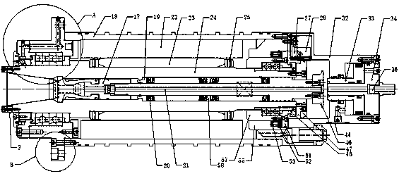
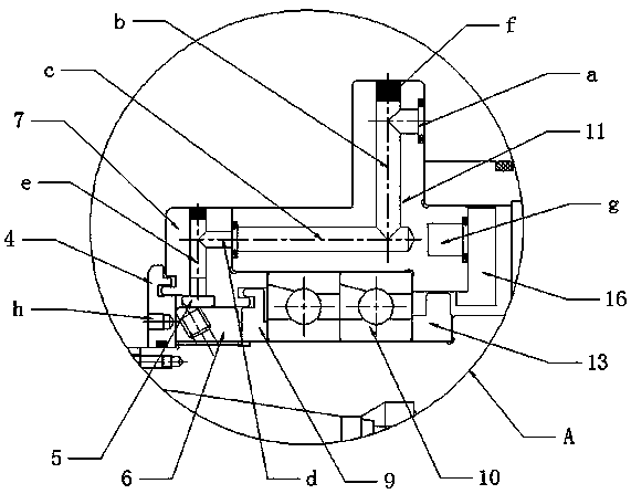
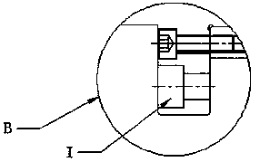
[0028] like Figure 1-8 As shown, it is a motor spindle of the present invention, comprising an end key 2, a waterproof ring 4, an air ring 5, a front locking nut 6, a front cover 7, a front labyrinth ring 9, an angular contact bearing 10, a front bearing seat 11, Front spacer 13, sealing ring 16, broach clamping jaw 17, sleeve 18, disc front spacer 19, disc spring 20, tie rod 21, motor stator 22, motor rotor 23, mandrel 24, rotor spacer 25, Encoder mounting plate 27, encoder 29, cylinder liner 32, piston 33, cylinder cover 34, trachea quick-insertion straight-through joint 36, bulky head 44, knife block 46, coding wheel 47, rear locking nut 48, rear bearing seat cover 51. Rear adjustment ring 52, compression spring 53, angular contact bearing 10, rear cover 55, rear bearing seat 57, disc spacer ring 58.

[0029] The motor stator 22 of the pr...


PUM


Abstract

The invention discloses a motor main shaft. The motor main shaft comprises a waterproof ring, a front cover, an angular contact bearing, a front bearing pedestal, a sleeve, a disc spring, a pull rod,a motor stator, a motor rotor, a core shaft, an encoder mounting plate, an encoder, an oil cylinder sleeve, a piston, an oil cylinder cover, a cutter block, an encoding wheel, a rear cover and a rearbearing pedestal; the motor rotor is integrated with the core shaft, and the motor stator is fixedly connected with the sleeve; the front bearing pedestal and the rear cover are arranged at the two ends of the sleeve; the sleeve is in rotation connection with the core shaft through the front bearing pedestal, the rear bearing pedestal and the angular contact bearing; the front cover is arranged atthe front end of the front bearing pedestal; the oil cylinder sleeve is arranged at the rear end of the rear cover; the piston is arranged in the oil cylinder sleeve; the oil cylinder cover is arranged at the rear end of the oil cylinder sleeve; the piston is located at the rear end of the pull rod, and the cutter block is arranged at the tail end of the pull rod; the encoder mounting plate is installed on the rear cover; the encoder is installed on the encoder mounting plate; the encoding wheel is installed at the tail end of the core shaft; and the pull rod and the disc spring are arrangedin a central hole of the core shaft. According to the motor main shaft, the rotating speed, stability and rigidity of the main shaft are improved, and the space is saved.

Description

technical field [0001] The invention relates to the technical field of machine tool processing equipment, in particular to a motor spindle. Background technique [0002] The spindle of the machining center is one of the cores of the entire machine tool. After it is equipped with a motor and a transmission device, it can perform various processes such as milling, boring, drilling, and tapping on the workpiece. The accuracy of the spindle often determines the machining accuracy of the workpiece. At present, the main shaft transmission mode adopts belt transmission, which has slow speed and low processing efficiency and precision. SUMMARY OF THE INVENTION [0003] The technical problem to be solved by the present invention is to provide a motor spindle, which can improve the rotational speed, stability, rigidity and space saving of the spindle. [0004] In order to solve the above-mentioned technical problems, the present invention adopts the following technical solutions: a...

Claims


Application Information

Patent Timeline
Patent Type & Authority Applications(China)
IPC IPC(8): H02K7/00H02K5/16H02K9/00H02K9/19H02K11/21
CPCH02K5/16H02K7/003H02K9/00H02K9/19H02K11/21
Inventor 葛建国石优国魏特丁嘉男王濠
Owner SWIFT NANTONG PRECISION MACHINERY
Why Eureka
Try Eureka