
Energy-saving variable-frequency and variable-speed motor

A frequency conversion motor, energy-saving technology, applied in electrical components, electromechanical devices, electric components, etc., can solve the problems of rising energy consumption, simple motor structure, low heat dissipation efficiency, etc., to avoid rising energy consumption and improve heat dissipation capacity. , to ensure the effect of heat dissipation

Inactive Publication Date: 2019-03-01
王钧
View PDF0 Cites 3 Cited by
  • Summary
  • Abstract
  • Description
  • Claims
  • Application Information

AI Technical Summary

Problems solved by technology

[0002] The motor is a common electrical device that can convert energy into kinetic energy. However, the traditional motor is often simple in structure and lacks relevant safety protection equipment. It is easy to cause the motor to overheat and damage the inside of the motor, and the speed cannot be changed. The heat dissipation efficiency is low, making the motor prone to failure;
[0003] Most of the existing frequency conversion motors are equipped with fan blades on the main shaft, so that the fan blades rotate with the main shaft, thereby dissipating heat from the motor itself. When the temperature is high, the spindle speed has to be increased to cool down, resulting in an increase in energy consumption

Method used


Image

  • Energy-saving variable-frequency and variable-speed motor
  • Energy-saving variable-frequency and variable-speed motor
  • Energy-saving variable-frequency and variable-speed motor

Examples


Embodiment Construction

[0030] The following will clearly and completely describe the technical solutions in the embodiments of the present invention with reference to the accompanying drawings in the embodiments of the present invention. Obviously, the described embodiments are only some, not all, embodiments of the present invention. Based on the embodiments of the present invention, all other embodiments obtained by persons of ordinary skill in the art without making creative efforts belong to the protection scope of the present invention.

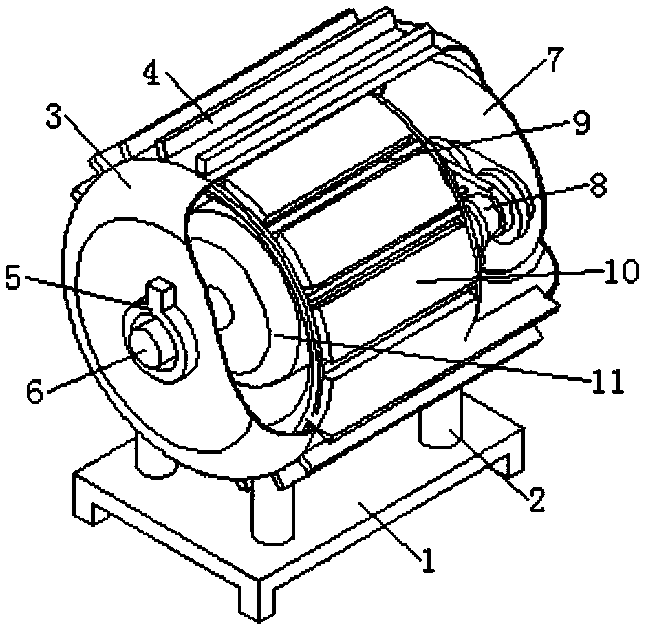
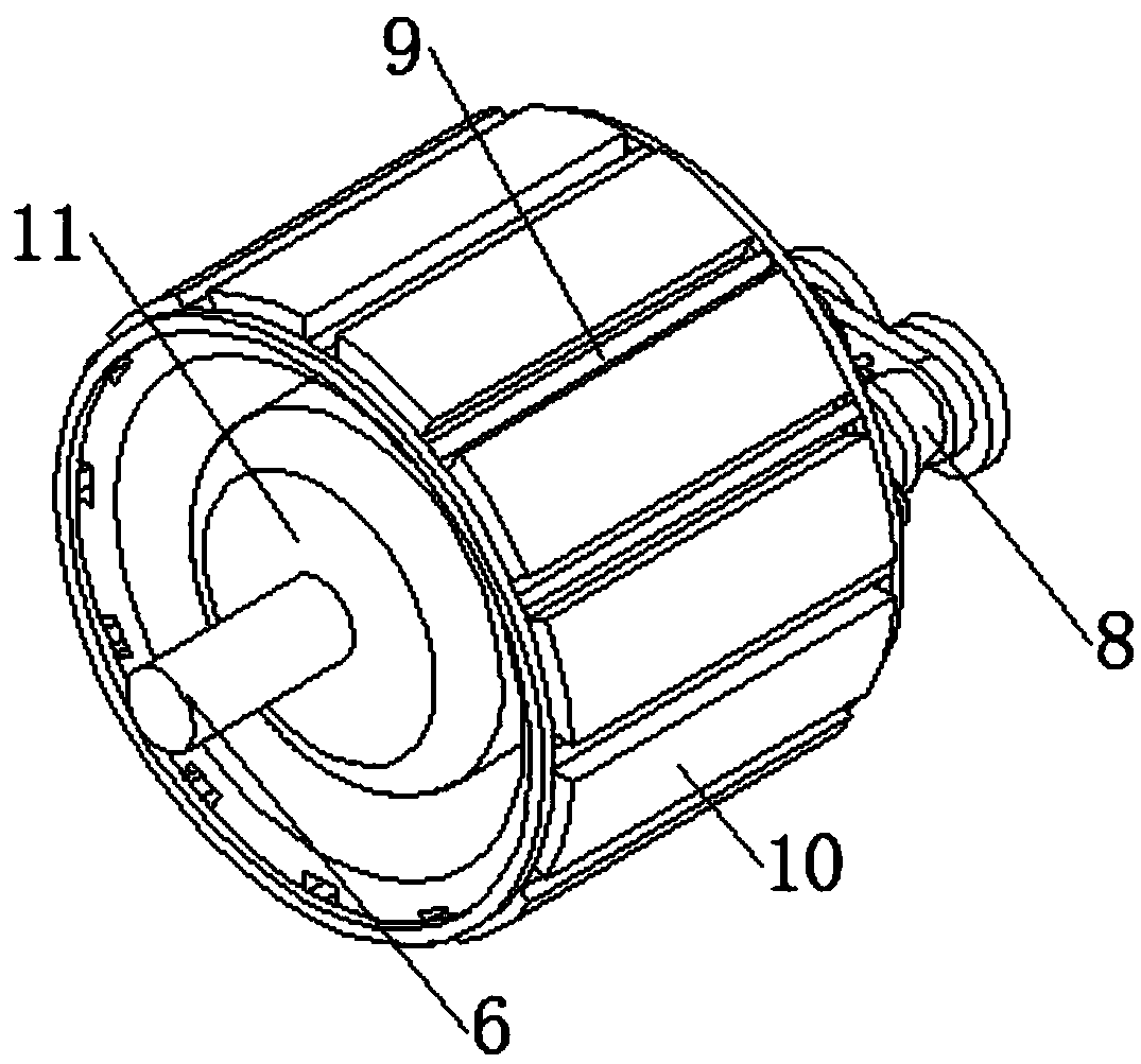
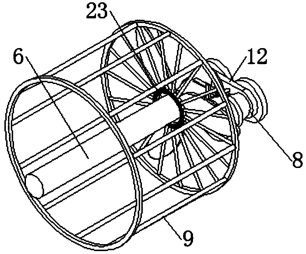
[0031] see Figure 1-8 , the present invention provides a technical solution: an energy-saving variable frequency speed regulation motor, including a main shaft 6, a rotor 11 is fixed outside the main shaft 6, and a stator 10 is arranged outside the rotor 11, and the stator 10 is fixedly installed on the inner wall surface of the housing 3, And the front end axis position of housing 3 is provided with bearing seat 5, and the front end of main shaft 6 cooperate...


PUM


Abstract

The invention discloses an energy-saving variable-frequency and variable-speed motor. The motor comprises a main shaft. The external of the main shaft is fixedly provided with a rotor, and a stator isarranged outside the rotor. The stator is fixedly mounted on an inner wall surface of a casing, and a front end axis position of the casing is provided with a bearing seat. The front end of the mainshaft is mounted with the bearing seat in a matched manner by a sliding bearing. An opening is arranged on the rear end of the casing, and a back net is arranged on the opening in a matched manner. Four vertical supporting columns are fixedly disposed on the lower end of the casing. The supporting column is installed in cooperation with a base, and the tail end of the main shaft is provided with aspeed regulating mechanism. The speed regulating mechanism is fixedly arranged with the casing by a mounting plate. The speed regulating mechanism is internally provided with fan blades. The energy-saving variable-frequency and variable-speed motor radiates heat by using the fan blades which can infinitely change speed in the casing, and changes of fan blade rotation speed is independent of changes of main shaft rotation speed, and the fan blade rotation speed is improved without through improving the main shaft rotation speed, and energy consumption is reduced.

Description

technical field [0001] The invention relates to the technical field of motors, in particular to an energy-saving variable frequency speed regulation motor. Background technique [0002] The motor is a common electrical device that can convert energy into kinetic energy. However, the traditional motor is often simple in structure and lacks relevant safety protection equipment. It is easy to cause the motor to overheat and damage the inside of the motor, and the speed cannot be changed. The heat dissipation efficiency is low, making the motor prone to failure; [0003] Most of the existing frequency conversion motors are equipped with fan blades on the main shaft, so that the fan blades rotate with the main shaft, thereby dissipating heat from the motor itself. When the temperature is high, the spindle speed has to be increased to cool down, resulting in an increase in energy consumption. Contents of the invention [0004] The technical problem to be solved by the present ...

Claims


Application Information

Patent Timeline
IPC IPC(8): H02K9/06H02K7/116H02K7/10H02K9/00H02K5/18H02K5/24
CPCH02K9/06H02K5/18H02K5/24H02K7/1004H02K7/116H02K9/00
Inventor 王钧
Owner 王钧
Learn More