Vehicle boundary crossing recognition and alarm method and system based on electronic fence

A technology of electronic fence and alarm system, which is applied to services based on location information, services based on specific environments, transmission systems, etc., can solve the problem of single use of electronic fence technology, inaccurate recognition of cross-border situations, and difficulty in handling concurrent vehicle events, etc. problems, to achieve the effect of high economic value and a wide range of applications

Inactive Publication Date: 2019-03-01
HAINAN YILE IOT TECH CO LTD
View PDF7 Cites 12 Cited by
  • Summary
  • Abstract
  • Description
  • Claims
  • Application Information

AI Technical Summary

Problems solved by technology

[0002] In the vehicle time-sharing leasing industry, electronic fence technology is used in many aspects, such as the determination of the return area, the determination of whether the rental vehicle leaves the specified use area, whether the rental vehicle enters or exits a specified area, etc. At present, the use of electronic fence technology in the market is still relatively simple, and often only a single type of alarm for driving out or driving in can be realized. The recognition effect for complex cross-border situations is not accurate, and it is difficult to deal with concurrent events of a large number of vehicles crossing the border.

Method used


Image

  • Vehicle boundary crossing recognition and alarm method and system based on electronic fence
  • Vehicle boundary crossing recognition and alarm method and system based on electronic fence
  • Vehicle boundary crossing recognition and alarm method and system based on electronic fence

Examples


Embodiment 1

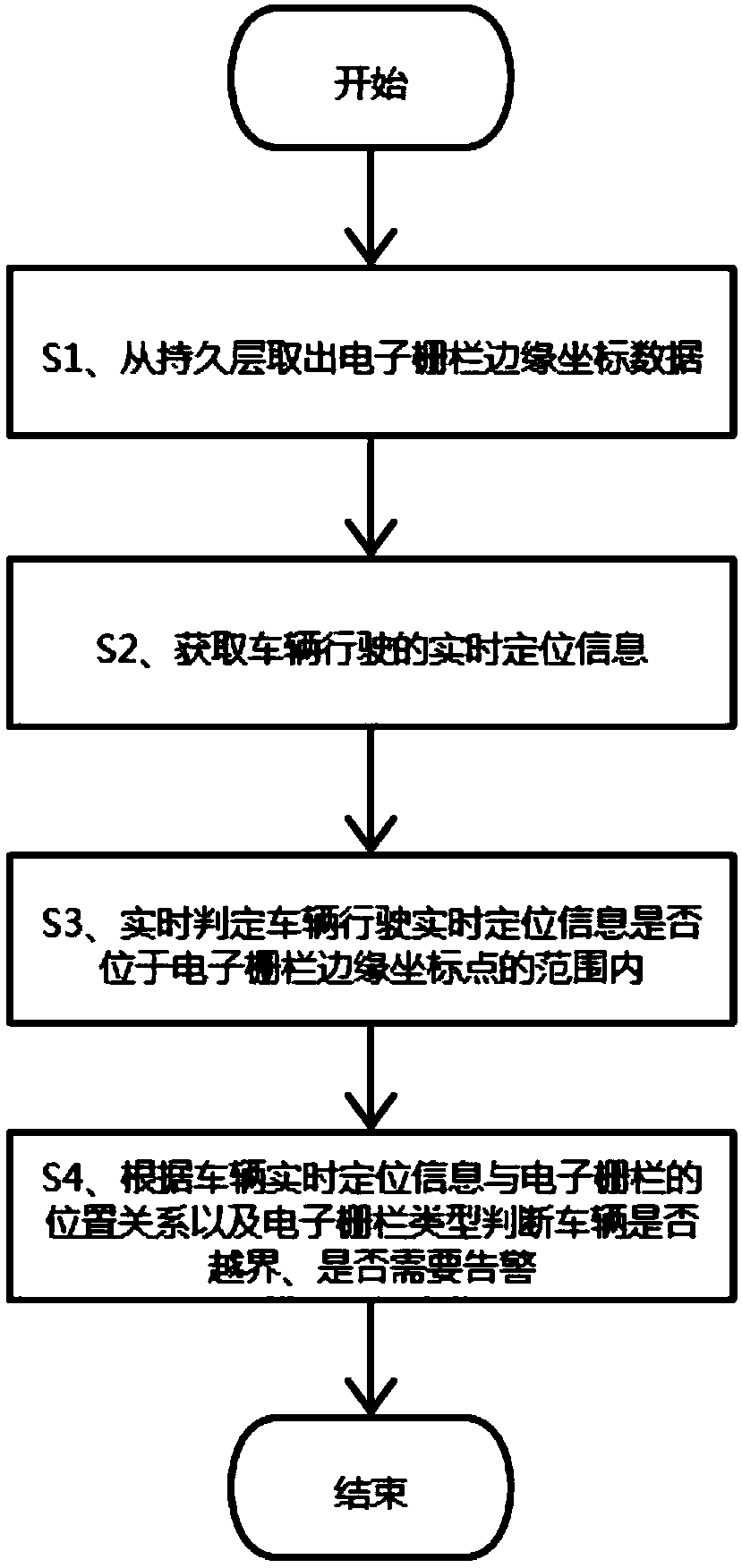
[0037] refer to figure 1 , the present invention provides a kind of vehicle cross-border recognition warning method based on electric fence, specifically comprises the following steps:

[0038] S1. Take out the edge coordinate point data of the electronic fence from the persistent layer.

[0039] The electronic fence refers to a specified area on the map, and the area can be represented as a closed figure of any shape. In this step, the edge coordinate point data forming the boundary of the electronic fence is obtained from the persistent layer responsible for data persistence.

[0040] S2. Obtain real-time positioning information of the vehicle.

[0041] In this step, the real-time positioning information of the vehicle is obtained through a mobile smart terminal or a vehicle-mounted positioning device, the mobile smart terminal is a smart phone supporting a positioning function, and the real-time positioning information includes at least the current coordinate point informa...

Embodiment 2

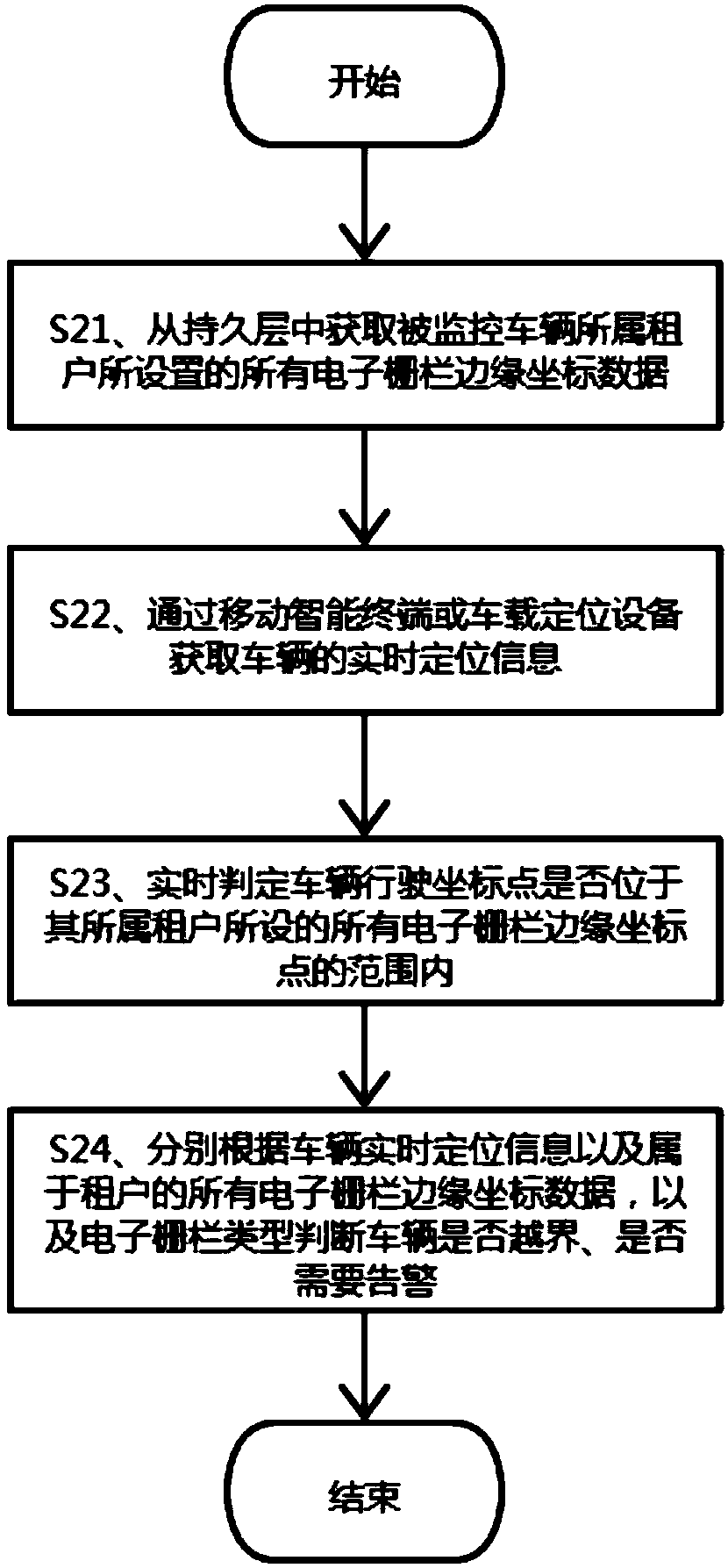
[0047] refer to figure 2 , the present embodiment provides a method for identifying and alerting a vehicle crossing a boundary based on an electronic fence. , the setting includes at least setting the number and boundary of the electronic fence, and can determine whether the vehicle crosses the boundary and whether to give an alarm based on the real-time positioning information of the vehicle leased by the tenant and all the electronic fences belonging to the tenant, specifically including the following steps:

[0048] S21. Obtain all electronic fence edge coordinate data set by the tenant to which the monitored vehicle belongs from the persistence layer.

[0049] In this step, there may be multiple electronic fences, and the shapes and types of the electronic fences may be different.

[0050] S22. Obtain the real-time positioning information of the vehicle through a smart mobile terminal or a vehicle positioning device.

[0051] S23. Determine in real time whether the driv...

Embodiment 3

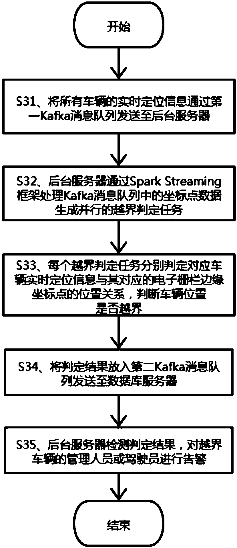
[0056] refer to image 3 , a kind of vehicle boundary-crossing recognition and warning method based on electronic fence provided in this embodiment, on the basis of above-mentioned embodiment, based on Spark Streaming frame and Kafka message queue, realizes the processing of concurrent large-scale vehicle boundary-crossing event, can simultaneously Judging the cross-border events such as a large number of vehicles driving out and entering, specifically includes the following steps:

[0057] S31. Send the real-time positioning information of all vehicles to the background server through the first Kafka message queue.

[0058] S32. The background server processes the coordinate point data in the Kafka message queue through the Spark Streaming framework to generate a parallel out-of-bounds judging task.

[0059] S33. Each border-crossing judging task judges the positional relationship between the real-time positioning information of the corresponding vehicle and its correspondin...


PUM


Abstract

The invention discloses a vehicle boundary crossing recognition and alarm method and system based on an electronic fence. The method comprises the following steps: extracting edge coordinate point data of the electronic fence from a persistent layer; acquiring real-time running location information of a vehicle; judging whether the real-time running location information of the vehicle is within the range of edge coordinate points of the electronic fence or not in real time; and judging whether the vehicle crosses a boundary or not and whether alarm needs to be made or not according to a position relationship between the real-time location information of the vehicle and the electronic fence. The system comprises a vehicle location unit, a background server and a database server. The methodand the system can process vehicle boundary crossing recognition and alarm events under various complex conditions in real time, can be applied to the aspects of determination of return areas of time-sharing leased vehicles, restriction of the use areas of the leased vehicles, statistics of the running area data of vehicles and the like, and have a wide application range and relatively high economical value.

Description

technical field [0001] The invention relates to the technical field of vehicle leasing management, in particular to a method and system for identifying and warning a vehicle crossing a boundary based on an electronic fence. Background technique [0002] In the vehicle time-sharing leasing industry, electronic fence technology is used in many aspects, such as the determination of the return area, the determination of whether the rental vehicle leaves the specified use area, whether the rental vehicle enters or exits a specified area, etc. At present, the use of electronic fence technology in the market is still relatively simple, and often only a single type of alarm for driving out or driving in can be realized. The recognition effect for complex cross-border situations is inaccurate, and it is difficult to deal with concurrent events of a large number of vehicles crossing the border. Contents of the invention [0003] In view of this, the object of the present invention i...

Claims


Application Information

Patent Timeline
Patent Type & Authority Applications(China)
IPC IPC(8): H04W4/021H04W4/40H04L29/08G08B21/18G06Q30/06
CPCH04W4/021H04W4/40G06Q30/0645G08B21/18H04L67/52
Inventor 李小平
Owner HAINAN YILE IOT TECH CO LTD
Why Eureka
Try Eureka