Impulse noise detection and removal for radar and communication systems

A radar system, impact noise technology, applied in the field of radar systems, can solve the problem of reducing signal-to-noise ratio

Pending Publication Date: 2019-03-01
RAYTHEON CANADA LTD
View PDF6 Cites 2 Cited by
  • Summary
  • Abstract
  • Description
  • Claims
  • Application Information

AI Technical Summary

Problems solved by technology

However, even small shocks can significantly increase the

Method used


Image

  • Impulse noise detection and removal for radar and communication systems
  • Impulse noise detection and removal for radar and communication systems
  • Impulse noise detection and removal for radar and communication systems

Examples


Embodiment Construction

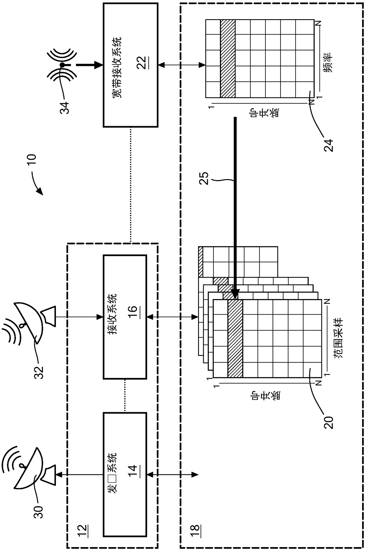
[0032] The described embodiments relate to systems and methods for implementing pulsed radar with narrowband signals, identifying impulsive noise using wideband data detection and analysis, and canceling the identified impulsive noise from narrowband radar signals.

[0033] refer to figure 1 A system 10 that combines broadband detection of impact events and narrowband target detection to provide noise cancellation includes a radar scanning system 12 having a radar transmitter system 14 and a narrowband radar receiver system 16 . Transmit and receive antennas 30, 32 are coupled to respective ones of transmit and receive systems 14, 16, respectively. In an embodiment, the transmit and receive antennas 30, 32 may be the same commonly known antenna.

[0034] Radar scanning system 12 is controlled by radar processor 18 which uses receiver system 16 to receive and store radar data from radar scanning. In an embodiment, the transmitting system 14 may be provided as a pulse-Doppler...


PUM


Abstract

A radar system including a narrowband radar receiver configured to receive pulsed radar return signals and a wideband receiver configured for receiving wideband signals. A noise data processor is configured to identify impulse noises by analyzing wideband signals received by the wideband receiver and a radar processor is configured to cancel the identified impulse noises from pulse signals received by the radar receiver. The wideband impulse noises utilized to cancel noise from the pulse signals corresponds to the same time period sweep of detection as that of the pulse signals.

Description

[0001] Cross References to Related Applications [0002] This application claims priority to US Provisional Application Serial No. 61 / 349,799, filed June 14, 2016, the entire contents of which are incorporated herein by reference. Background technique [0003] Jamming can be a major impediment to the operational performance of radar systems. A common source of interference is impulsive noise, which may occur, for example, due to area lighting discharges or local man-made noise sources. Impulse noise is characterized as having a short duration and thus affects only a small part of the pulse time series. However, for systems that integrate signals detected over long periods of time, such short-duration disturbances can lead to increased noise throughout the integration segment. Traditional methods for mitigating signal attenuation caused by impulsive noise rely on detecting and removing corrupted pulses and using various techniques to limit frequency leakage across the signal ...

Claims


Application Information

Patent Timeline
IPC IPC(8): G01S7/32
CPCG01S7/023G01S7/2928G01S7/021G01S7/292G01S7/4021G01S7/2813G01S13/0209
Inventor R·麦克拉切尔A·M·庞斯福德
Owner RAYTHEON CANADA LTD
Why Eureka
Try Eureka