Improved ankle prosthesis

A technology of prosthesis and ankle prosthesis, applied in the field of ankle prosthesis, can solve problems such as high mechanical stress

Active Publication Date: 2019-03-05
IN2BONES
View PDF3 Cites 2 Cited by
  • Summary
  • Abstract
  • Description
  • Claims
  • Application Information

AI Technical Summary

Problems solved by technology

Furthermore, blocking of the ankle joint leads to high mechanical stress on the adjacent joint, which then exposes to a high risk of early degeneration

Method used


Image

  • Improved ankle prosthesis
  • Improved ankle prosthesis
  • Improved ankle prosthesis

Examples


Embodiment Construction

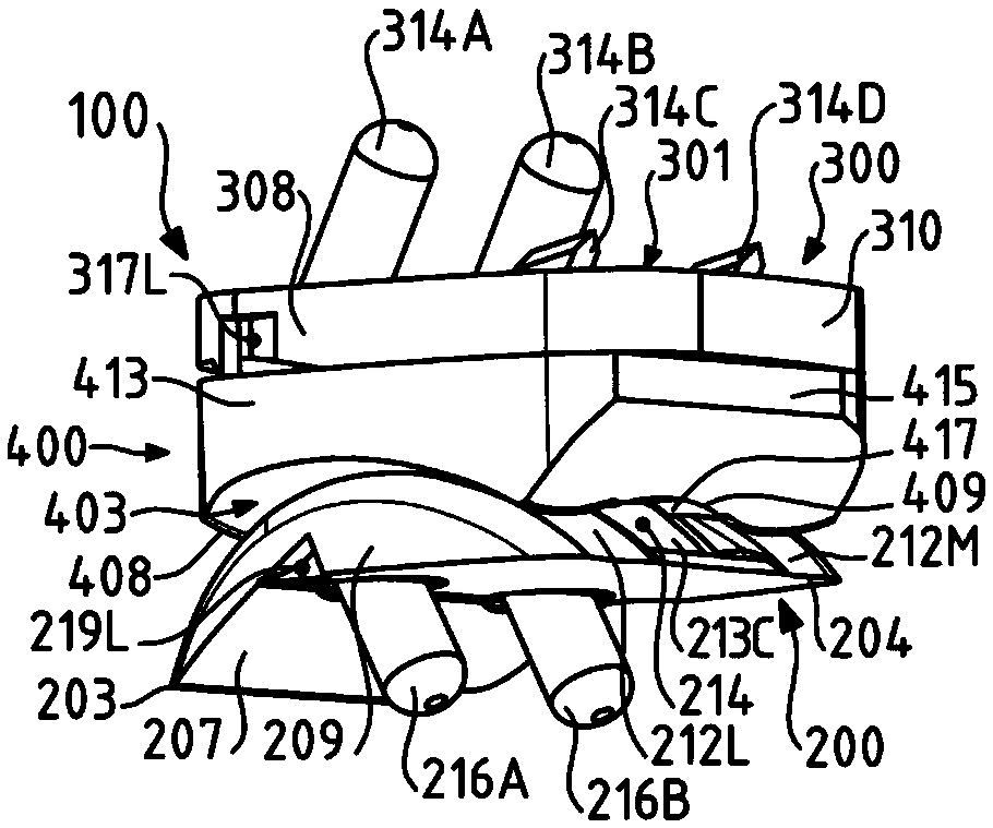
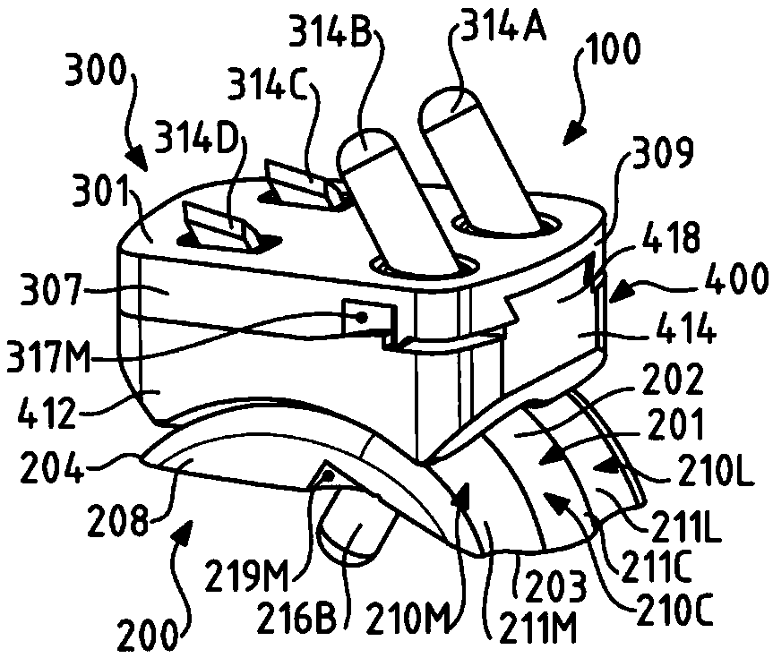
[0026] The present invention relates to an ankle prosthesis 100 comprising figure 1 and figure 2 The preferred embodiment shown in . The prosthesis 100 constitutes a device surgically implantable in the body of a human or animal patient for the replacement of a specific ankle joint. Advantageously, said prosthesis 100 is designed to completely replace the associated ankle joint (total ankle prosthesis, TAP). Thus, the prosthesis 100 according to the invention is designed to be inserted between the lower end of the tibia and the corresponding talus of the patient's foot. Advantageously, prior to fitting the prosthesis 100 according to the invention in the patient's body, the tibia and talus under consideration will undergo sufficient preparation, such as extraction of cartilage elements and bone segments, in order to remove the ankle joint to be replaced All or part of the natural articular surface.

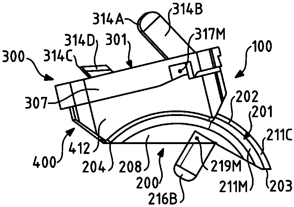
[0027] exist Figure 1 to Figure 5 The prosthesis 100 shown as an examp...


PUM


Abstract

The present invention relates to a sacral prosthesis (100) comprising a talar component (200) which comprises a talar top (201) defining a first joint surface (202) and extending between a talar anterior edge (203) and an opposite talar posterior edge (204) along a first average direction; the first joint surface (202) is curved in the first average direction; the first joint surface (202) includes a first curved portion (202A) and a second curved portion (202B) each extending along the first average direction; the first curved portion (202A) has a first curvature, and the second curved portion (202B) has a second curvature; the prosthesis (100) is characterized in that the first curved portion (202A) and the second curved portion (202B) define a front portion and a rear portion of the first joint surface (202), respectively. The first curvature is greater than the second curvature.

Description

technical field [0001] The present invention relates to the general field of ankle prostheses, ie implantable devices for replacing ankle joints, particularly in the context of orthopedic treatment. [0002] The present invention relates more particularly to an ankle prosthesis comprising a talar component comprising a talar upper face defining a first articular surface and extending according to a first mean direction between an anterior edge of the talus and an opposite posterior edge of the talus, said first An articular surface curves along the first mean direction. Background technique [0003] In order to treat some bony lesions of the ankle, such as osteoarthritis, which cause degeneration or disappearance of the articular cartilage, arthrodesis of the ankle joint is known to be performed. This arthrodesis procedure is aimed at limiting or even completely blocking the mobility of the ankle through osteosynthesis in order to prevent joint pain felt by the patient. Al...

Claims


Application Information

Patent Timeline
Patent Type & Authority Applications(China)
IPC IPC(8): A61F2/42
CPCA61F2/4202A61F2002/4207A61F2002/4205A61F2230/00A61F2002/30205A61F2002/30327A61F2002/30387A61F2002/30841A61F2002/30878A61F2002/30934A61F2002/30889A61F2002/30892A61F2/30749A61F2002/30131A61F2002/3021A61F2002/30518A61F2002/30621
Inventor 蒂博·琼·皮埃尔·亨利·莱姆里耶斯皮特·普特西斯洛朗·弗朗索瓦·雷内·保罗佩-亨里克·阿格伦让-吕克·皮埃尔·玛丽·贝丝
Owner IN2BONES
Why Eureka
Try Eureka