
Thick plate head first-shearing positioning device and control method

A technology for positioning devices and heads, which is applied in the direction of shearing devices, shearing machine control devices, and shearing machine attachments, etc., can solve the problems of inability to effectively locate the end of the steel plate and low positioning accuracy, and achieve the realization of thick plate shearing. Cutting automation, precise positioning control, and simple equipment configuration

Active Publication Date: 2019-03-05
BAOSHAN IRON & STEEL CO LTD
View PDF8 Cites 3 Cited by
  • Summary
  • Abstract
  • Description
  • Claims
  • Application Information

AI Technical Summary

Problems solved by technology

[0007] In order to overcome the defect of the low precision of the first knife shearing positioning of the shearing head of the thick plate cutting head, the present invention proposes a first knife shearing positioning device and its control method of the thick plate cutting head, using the light curtain and the cutting head The joint control of the original length measuring rollers of the shears realizes the high-precision positioning of the first cutting of the thick plate head, effectively solving the hysteresis of the length measurement and positioning control of the single length measuring rollers of the cutting head shears and the inability to effectively locate the maximum value of the steel plate The serious disadvantage of the head end, which significantly improves the positioning accuracy of the head of the thick plate

Method used

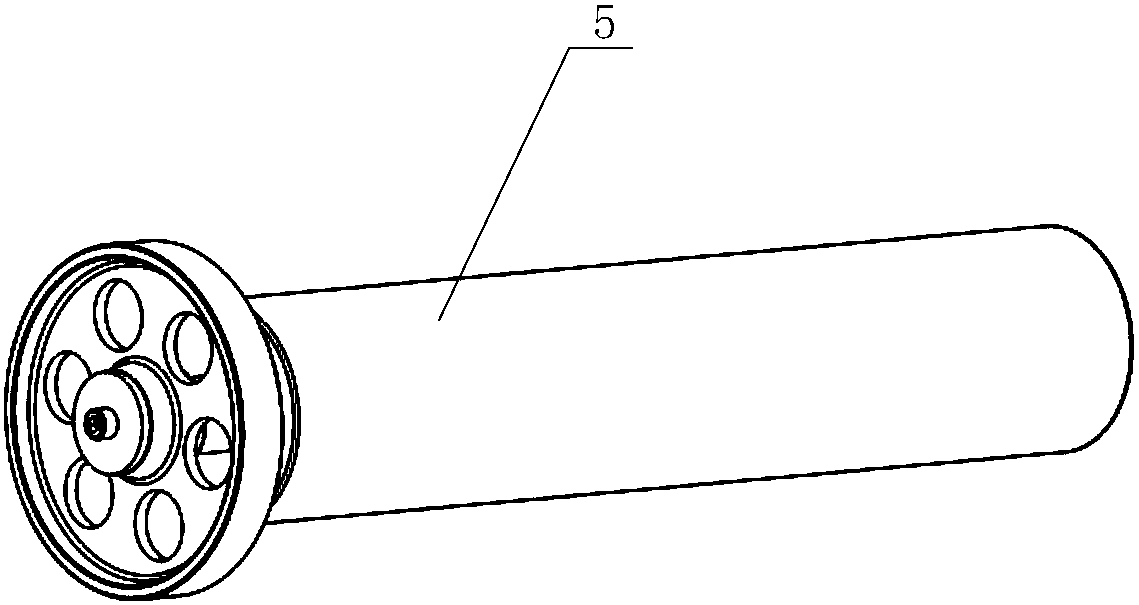
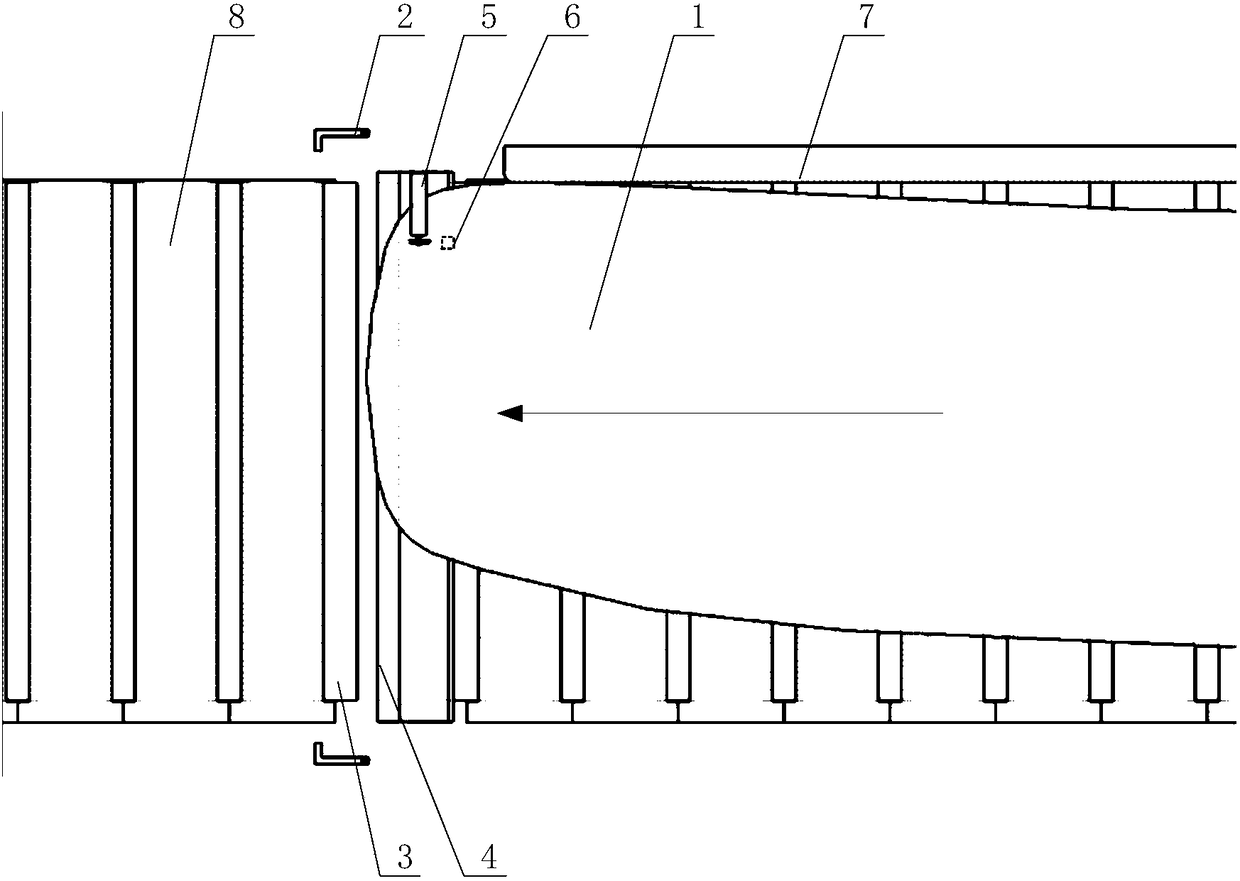
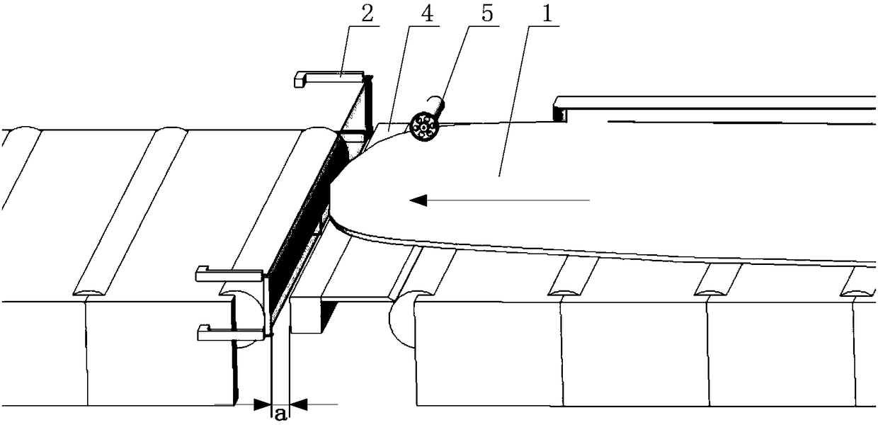

Image

  • Thick plate head first-shearing positioning device and control method
  • Thick plate head first-shearing positioning device and control method
  • Thick plate head first-shearing positioning device and control method

Examples


Embodiment Construction

[0038] In order to make the purpose, technical solutions and advantages of the embodiments of the present invention clearer, the technical solutions in the embodiments of the present invention will be clearly and completely described below in conjunction with the drawings in the embodiments of the present invention. Obviously, the described embodiments It is a part of embodiments of the present invention, but not all embodiments. Based on the embodiments of the present invention, all other embodiments obtained by persons of ordinary skill in the art without creative efforts fall within the protection scope of the present invention.

[0039] to combine figure 2, the direction of the arrow in the figure is the conveying direction of the steel plate 1 to be sheared by the cutting head, a shearing and positioning device for the first knife at the head of a thick plate, including the steel plate 1 to be sheared, the light curtain 2, and the first roller of the swinging roller tabl...


PUM

PropertyMeasurementUnit
thicknessaaaaaaaaaa

Abstract

The invention provides a thick plate head first-shearing positioning device and control method, and relates to the technical field of automatic shearing control on thick plates. The device comprises head cutting shears, an output roller bed, a length measuring roller, an input roller bed, light curtains and a to-be-sheared steel plate; the to-be-sheared steel plate is placed on the input roller bed; the head cutting shears are mounted at the headmost end of the input roller bed; the length measuring roller is mounted on the head cutting shears; and the light curtains are mounted on a head cutting shear rack, are used in pairs and are arranged in a face-to-face manner. According to the device and the control method, through combined control by the aid of the light curtains and the originallength measuring roller of the head cutting shears, high-precision positioning of first shearing of the head of the thick plate is realized, the serious defects that the hysteresis exists during length measurement by the aid of the single length measuring roller of the head cutting shears and positioning control and the headmost end of the steel plate cannot be positioned effectively are overcomeeffectively, and the positioning precision of the head of the thick plate is improved remarkably.

Description

technical field [0001] The invention relates to the technical field of thick plate automatic shearing control, in particular to a first knife shear positioning device at the head of a thick plate and a control method thereof. Background technique [0002] The thick plate shears are used to cut the head and tail fillets of the rolled slab and to roughly cut the rolled slab into sections of suitable length for the subsequent operation. From the definition of its equipment function, the cutting head scissors itself does not have very high requirements for cutting precision control, so the precision control devices and control methods it is equipped with are relatively backward. [0003] However, due to the following reasons, the requirements for the shearing positioning accuracy of the head shears, especially the shearing positioning accuracy of the first knife at the head, are getting higher and higher: 1) The requirements for the yield of thick plates are getting higher and h...

Claims


Application Information

Patent Timeline
Patent Type & Authority Applications(China)
IPC IPC(8): B23D33/02B23D36/00
CPCB23D33/02B23D36/0008
Inventor 朱剑恩丁海绍
Owner BAOSHAN IRON & STEEL CO LTD
Learn More