
Machine tool

A machine tool and bed technology, applied in lathes, conveyors, metal processing machinery parts, etc., can solve the problems of workpiece scratches and large changes in manufacturing tolerances, and achieve the effect of reducing the installation area and reducing the risk of debris accumulation.

Active Publication Date: 2019-03-05
德克尔马霍塞巴赫公司
View PDF5 Cites 2 Cited by
  • Summary
  • Abstract
  • Description
  • Claims
  • Application Information

AI Technical Summary

Problems solved by technology

If metal shavings build up on the workpiece, it can result in unwanted scratches on the workpiece, or even more material than desired to be removed from the workpiece (due to metal shavings being introduced into the removal process), which May cause wide variations in manufacturing tolerances

Method used


Image

  • Machine tool
  • Machine tool
  • Machine tool

Examples


Embodiment Construction

[0039] The examples and exemplary embodiments of the present invention will be described in detail below with reference to the accompanying drawings. The same or similar elements in the drawings may be represented by the same reference numerals.

[0040] However, it is worth noting that the present invention is not limited or limited to the exemplary embodiments described below and their design features, but also includes changes to the exemplary embodiments, especially changes to the described examples The features of or the combination of single or several features of the described examples are all within the protection scope of the independent claims.

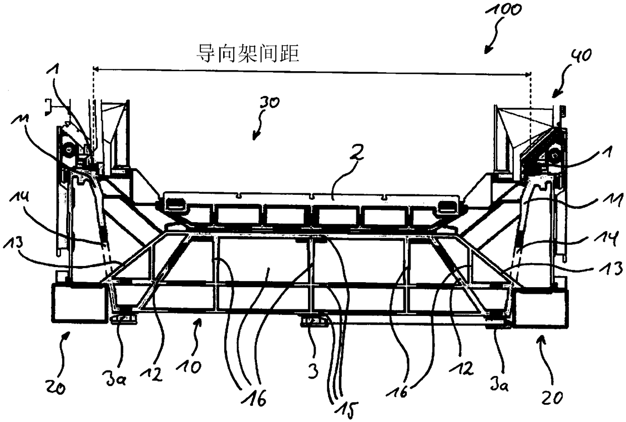
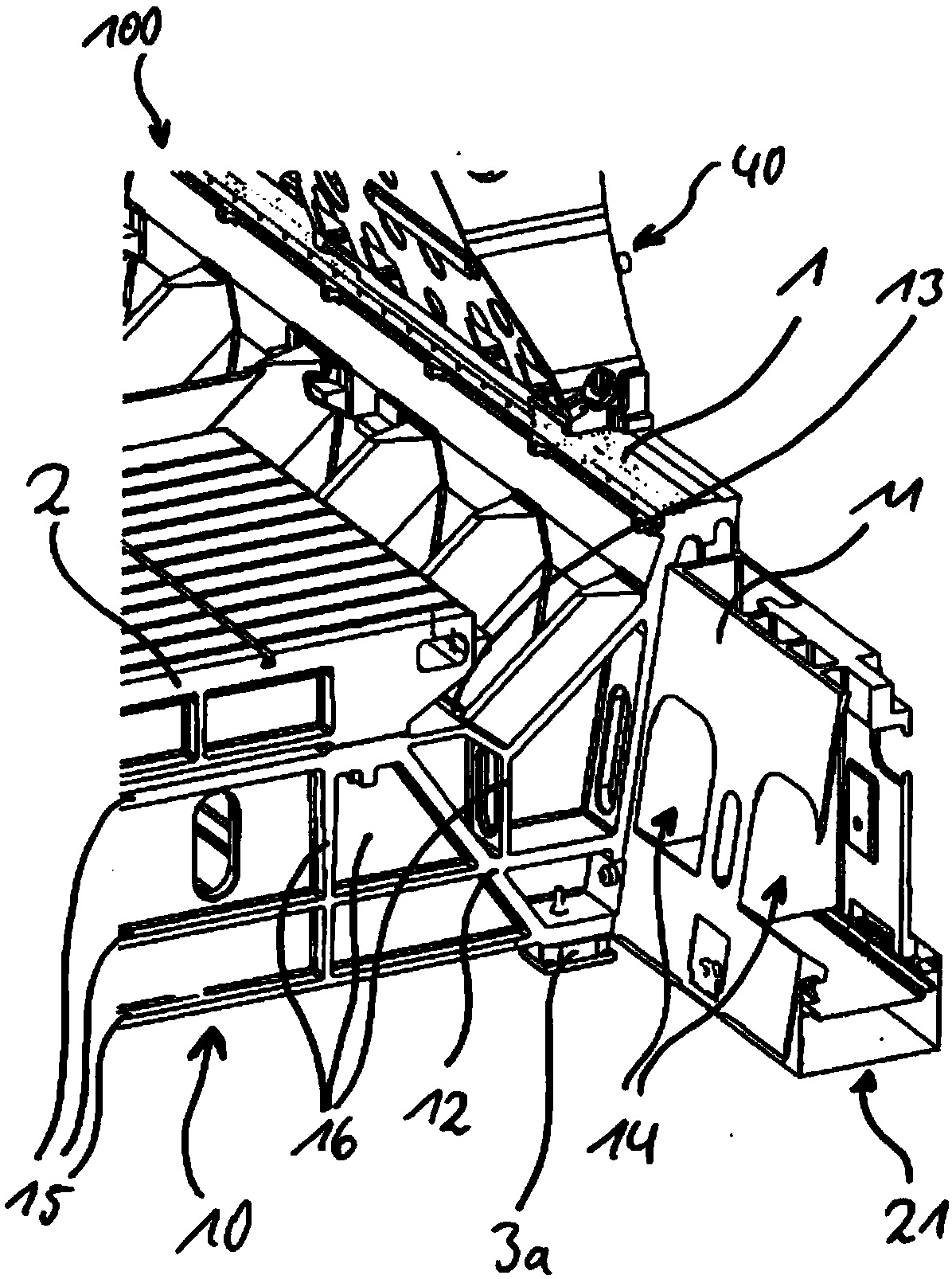
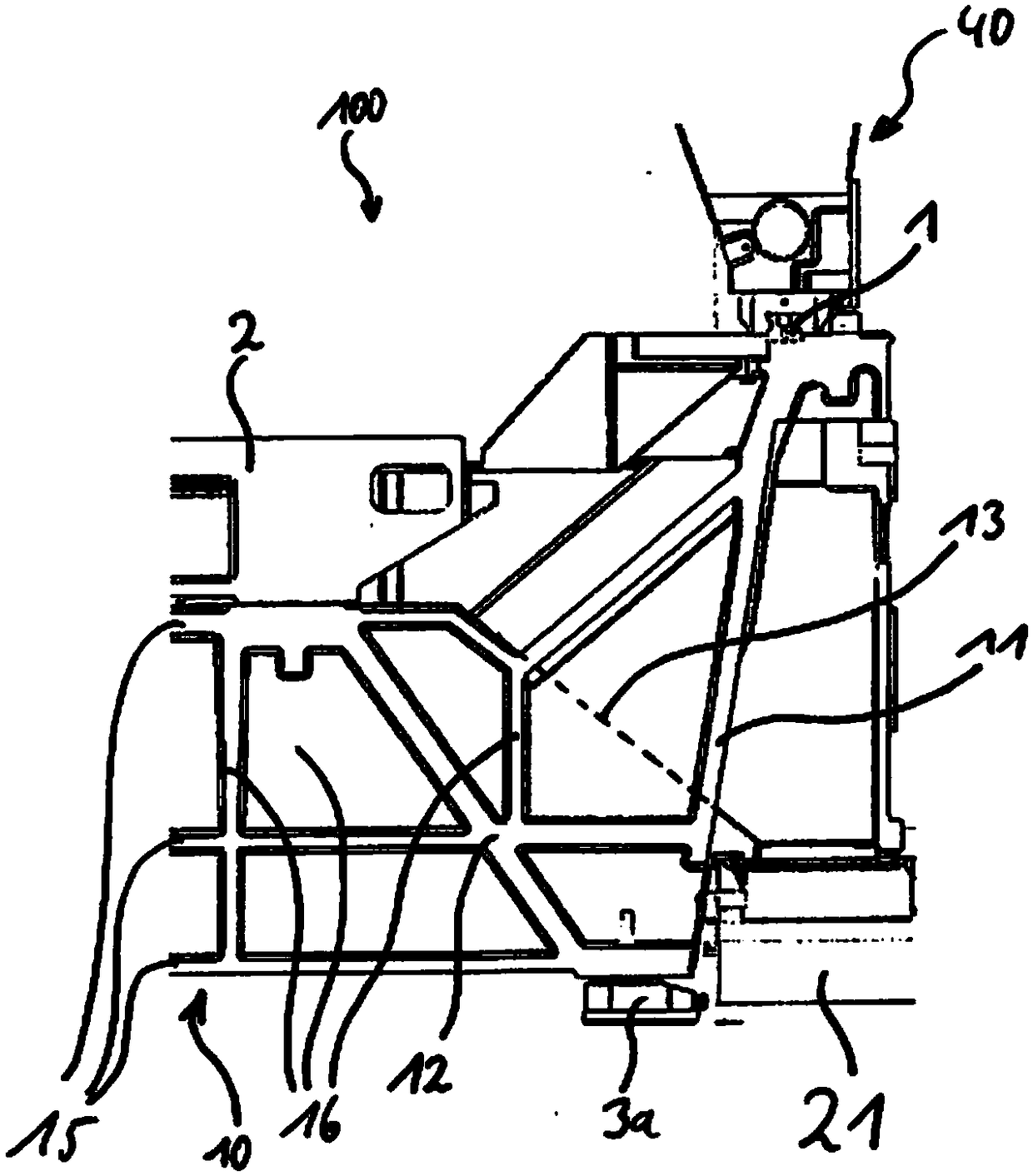
[0041] figure 1 Schematically shows an embodiment of the machine tool 100 according to the present invention. The machine tool 100 includes a first main rib 11, a second main rib 12, and a guide rib 13. The first main rib 11, the second main rib 12, and the guide rib 13 serve as a supporting structure. In the bed 10 of the machi...


PUM


Abstract

The present invention relates to a machine tool which has the following: a machine bed 10 which is supported on machine feet 3, 3a and is formed from a supporting structure of ribs which are connectedto one another, wherein two guide rails 1 are arranged on the top side, on opposite outer sides of the machine bed 10, and a machine table 2 is provided between the two guide rails 1, wherein first main ribs 11 are provided on either side of the machine bed 10, the profile of the said first main ribs, in cross section of the machine bed 10, beginning below the guide rails 1 and extending obliquely inwards in the machine bed 10 to external machine feet 3a in order to introduce loads, which act on the guide rails 1, into the machine feet 3, 3a.

Description

Technical field [0001] The invention relates to machine tools. Background technique [0002] In addition to the machining unit and the measuring system used by the machine tool, the machine bed is also one of the most important parts of the machine tool. Since the bed must absorb the force and load generated during the machining process through the corresponding rigidity, the bed plays an important role in the accuracy of the parts to be processed. This is especially true for relatively large machine tools that handle large numbers of heavy parts. In this case, the greater the rigidity of the bed, the more accurate the machining result. [0003] For this reason, an internal support structure is generally provided in the bed, which is used to maximize the stiffness while minimizing the amount of material used to form the bed. In addition, the support structure of the bed can have voids and channels for wiring or accessories that play an important role in normal operation. [0004]...

Claims


Application Information

Patent Timeline
Patent Type & Authority Applications(China)
IPC IPC(8): B23Q1/01B23Q11/00
CPCB23Q1/015B23Q11/00B23Q11/0042B23Q11/0053B65G17/00B65G33/08B23Q2701/00B65G2201/04B23Q11/0067Y10T82/2566Y10T408/50B23Q11/10
Inventor 费比安·祖克特
Owner 德克尔马霍塞巴赫公司
Learn More