
Power transmitting component including a limited slip differential

A technology of power transmission and differential case, applied in the direction of differential transmission, transmission parts, clutch, etc., can solve problems such as too large and complex

Active Publication Date: 2019-03-05
AMERICAN AXLE & MFG
View PDF6 Cites 0 Cited by
  • Summary
  • Abstract
  • Description
  • Claims
  • Application Information

AI Technical Summary

Problems solved by technology

Limited slip differentials capable of limiting the difference in output torque between two output sections are well known, but may be complex or too large for some applications

Method used


Image

  • Power transmitting component including a limited slip differential
  • Power transmitting component including a limited slip differential
  • Power transmitting component including a limited slip differential

Examples


Embodiment Construction

[0036] Example embodiments will now be described more fully with reference to the accompanying drawings.

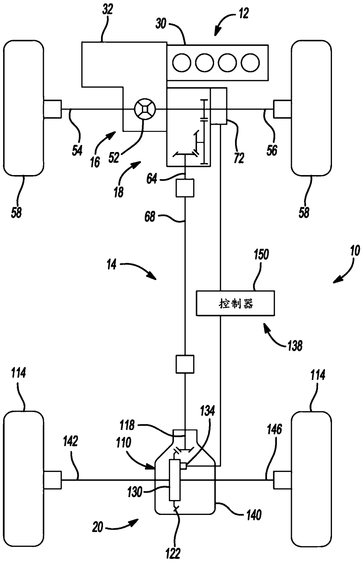
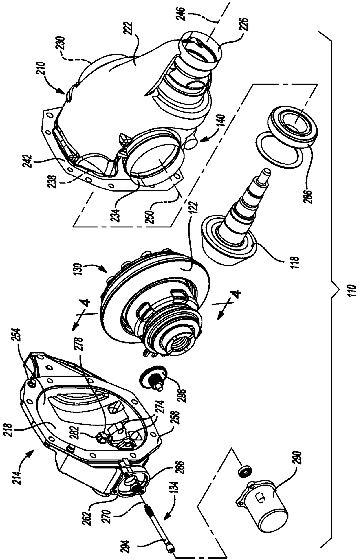
[0037] Refer to the attached figure 1 , an exemplary vehicle 10 is shown including a powertrain 12 and a transmission system 14 which may include a primary driveline 16 , a power take-off unit (PTU) 18 and a secondary driveline 20 . Powertrain 12 may include a prime mover 30 , such as an internal combustion engine or an electric motor, and a transmission 32 , which may be any type of transmission, such as a manual, automatic, or continuously variable transmission. Prime mover 30 may provide rotational power to transmission 32 , which outputs rotational power to main driveline 16 and PTU 18 . PTU 18 may be configured in any suitable manner to be selectively operated to transmit rotational power to auxiliary driveline 20 . For example, PTU 18 may be constructed as described in commonly assigned US Patent No. 8,961,353, the disclosure of which is incorporated herein by ref...


PUM


Abstract

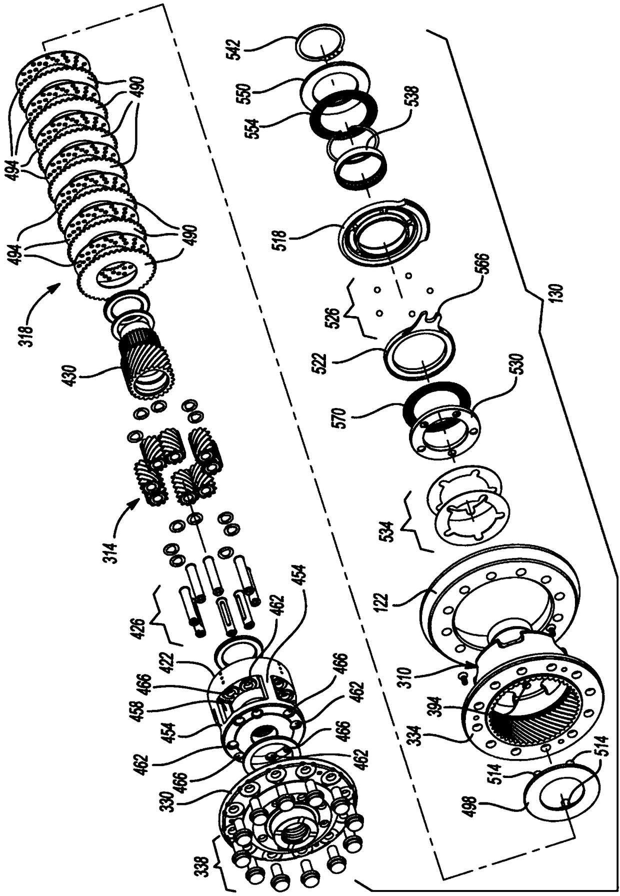
A power transmitting component comprising a limited slip differential is provided, which can include a planetary differential including a differential case. The planet carrier can be disposed within the differential case and rotatable about the output axis relative thereto. The first output member can be coupled to the planet carrier for common rotation about the output axis. The second output member can be coupled to the sun gear for common rotation about the output axis. A clutch basket can be fixedly coupled to the planet carrier and disposed within the differential case. A set of first friction plates can be coupled to the clutch basket for common rotation about the output axis therewith and for axial translation relative to the clutch basket. A set of second friction plates can be coupled to the sun gear for common rotation about the output axis and for axial translation relative to the sun gear.

Description

technical field [0001] The present disclosure relates to a power transmission component including a limited slip differential. Background technique [0002] This section provides background information related to the present disclosure which is not necessarily prior art. [0003] Modern motor vehicles typically include power transfer components including a differential configured to receive input torque and output differential torque to a pair of outputs. For example, a front differential or a rear differential may output differential torque to left and right drive wheels, or a center differential may output differential torque between a front drive system and a rear drive system. Limited slip differentials capable of limiting the difference in output torque between two outputs are well known, but may be complex or too large for some applications. For this reason, there is still a need in the art to develop improved limited-slip differentials. Contents of the invention ...

Claims


Application Information

Patent Timeline
Patent Type & Authority Applications(China)
IPC IPC(8): F16H48/06
CPCF16H48/06F16H57/037F16H48/11F16H48/22F16H48/40F16D13/683F16D2023/123F16D13/52F16D23/12
Inventor 保罗·J·瓦伦特詹姆斯·P·唐斯
Owner AMERICAN AXLE & MFG
Learn More