
New energy automobile simulation test system

A new energy vehicle, simulation test technology, applied in vehicle testing, machine/structural component testing, measuring devices, etc., can solve the problem of inability to analyze and evaluate overall performance, inability to effectively balance output stable pressure values ​​and stable flow values, safety hidden dangers

Pending Publication Date: 2019-03-05
深圳市万斯得自动化设备有限公司 +1
View PDF0 Cites 4 Cited by
  • Summary
  • Abstract
  • Description
  • Claims
  • Application Information

AI Technical Summary

Problems solved by technology

However, there is currently no complete detection system in China to simulate the actual use of new energy vehicle components (such as individual components such as radiators, water pumps, and heat sources) and assembly cooling systems (such as battery systems, control assemblies, and motor systems) performance, it is impossible to obtain effective actual simulated use data before putting into use, and it is impossible to analyze and evaluate the overall performance and control strategy, which greatly improves the performance of potential safety hazards in use
[0003] In the process of testing the general circulation equipment on the market, the pressure control of the circulation equipment on the market adopts the pump pressure control, and the flow control adopts the principle of pump frequency conversion flow control. Because the change of the pump pressure output will also lead to the change of the pump output flow, and During the test process, the two variables need to maintain the required set values ​​at the same time. In the case of meeting the pressure accuracy and flow accuracy, the control cannot effectively balance the output of high-precision stable pressure values ​​and stable flow values.
In addition, in the process of flow control, there is also a large difference between the flow detected by the main path and the flow detected by the branch path

Method used


Image

  • New energy automobile simulation test system
  • New energy automobile simulation test system
  • New energy automobile simulation test system

Examples


Embodiment Construction

[0023] In order to facilitate the understanding of the present invention, the present invention will be described more fully below with reference to the associated drawings. Preferred embodiments of the invention are shown in the accompanying drawings. However, the present invention can be embodied in many different forms and is not limited to the embodiments described herein. On the contrary, the purpose of providing these embodiments is to make the disclosure of the present invention more thorough and comprehensive.

[0024] It should be noted that when an element is referred to as being “fixed” to another element, it can be directly on the other element or there can also be an intervening element. When an element is referred to as being "connected to" another element, it can be directly connected to the other element or intervening elements may also be present. The terms "vertical," "horizontal," "left," "right," and similar expressions are used herein for purposes of ill...


PUM


Abstract

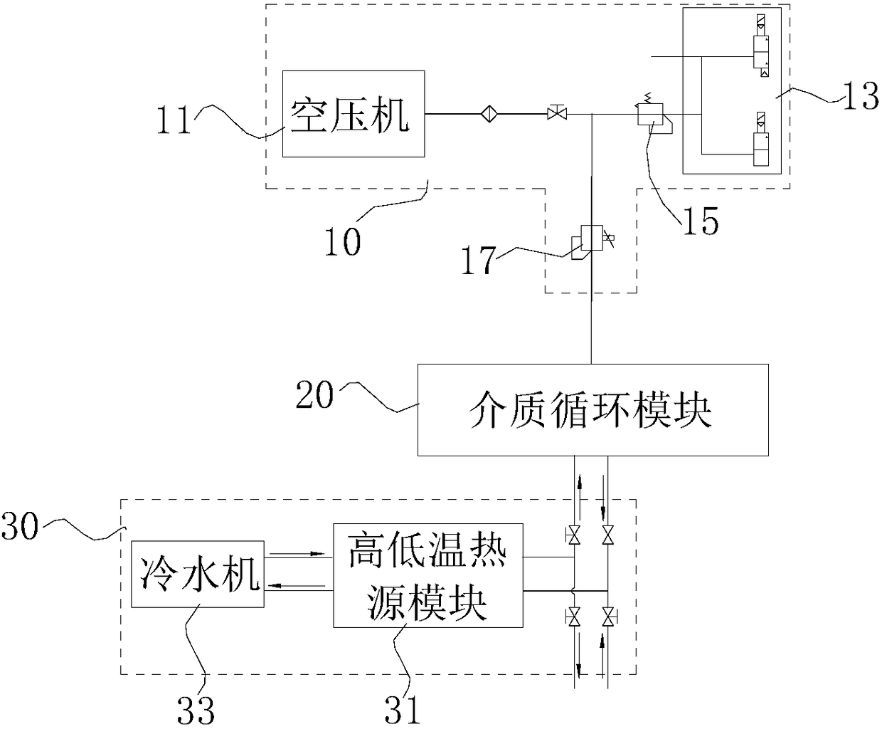
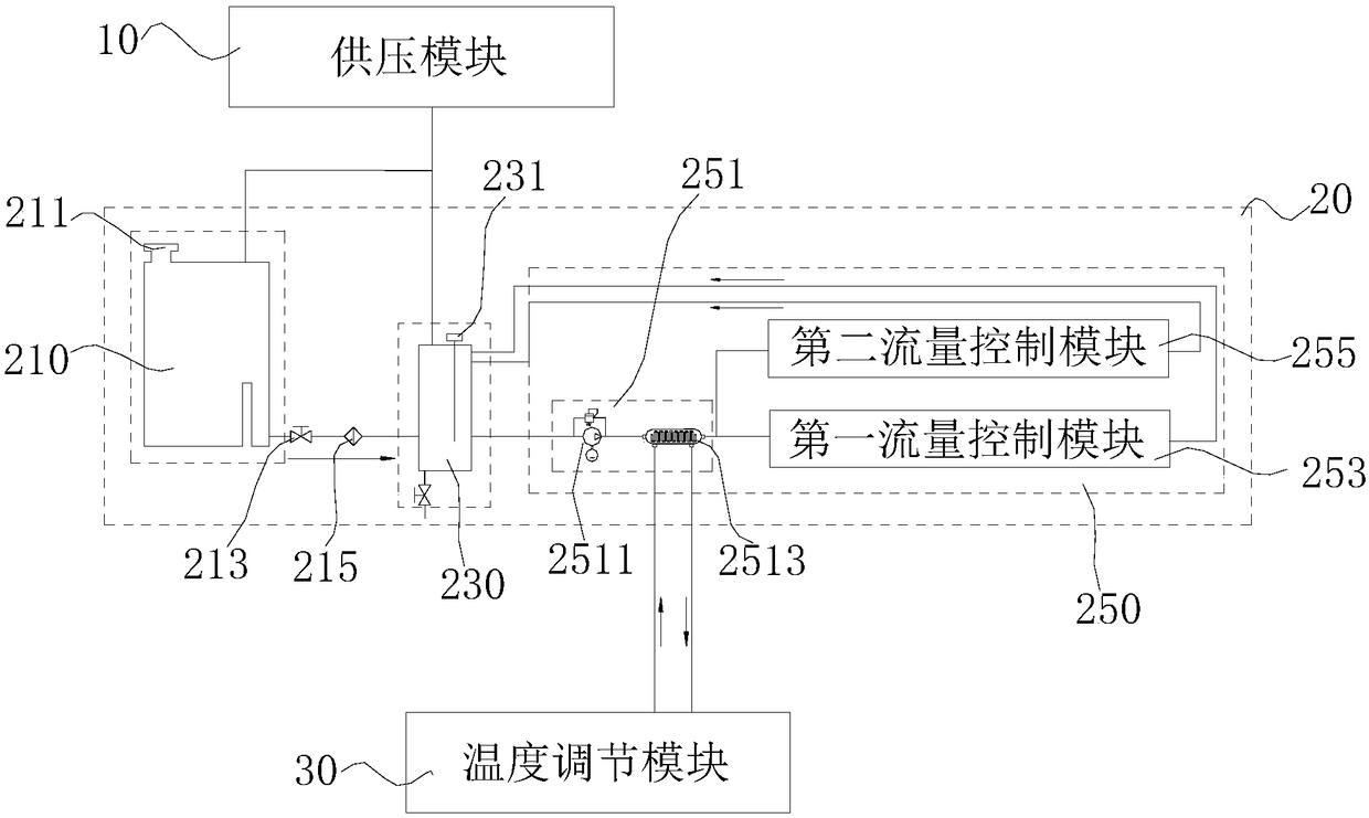
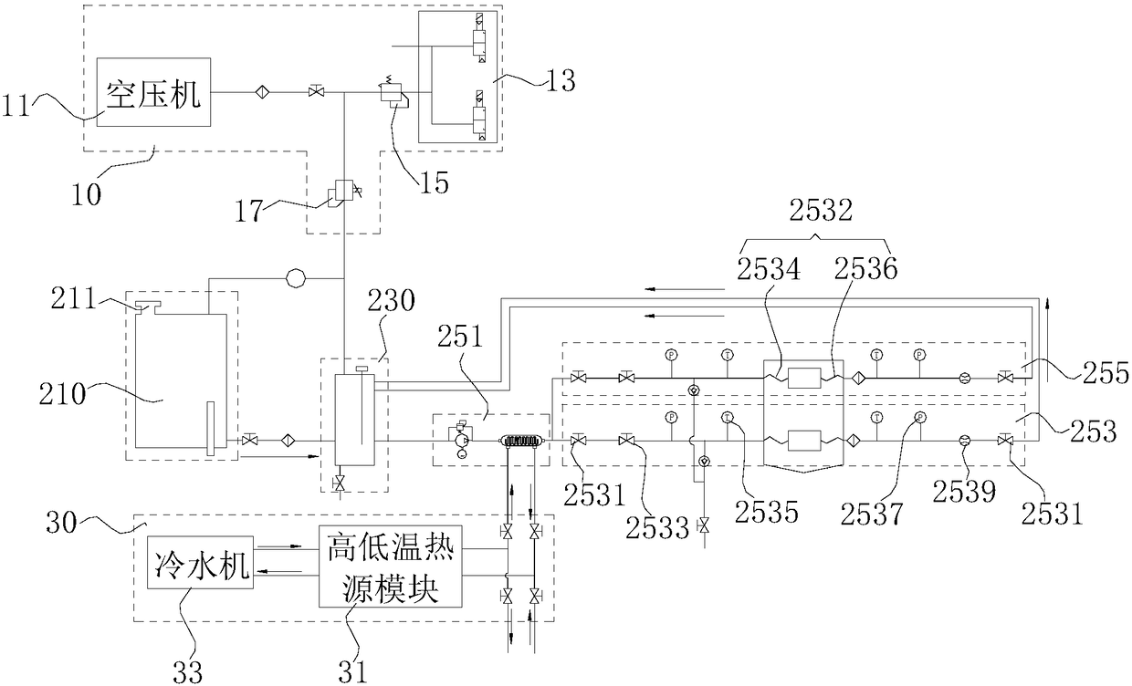
The invention relates to a new energy automobile simulation test system comprises a pressure supply module, a medium circulation module and a temperature adjustment module, wherein the pressure supplymodule includes a pressure control valve and adjusts the input pressure intensity through the pressure control valve; the medium circulation module includes a main capacity box, a liquid storage tank, a main path flow control module and a plurality of branch path flow control modules, the main capacity box is connected to the pressure control valve and is connected to the liquid storage tank, themain path flow control module is connected to the liquid storage tank, two ends of the branch path flow control module are respectively connected to the main path flow control module and the liquid storage tank, the branch path flow control modules automatically adjust the flow of branch paths respectively, and the main path flow control module adjusts the main path flow according to the feedbackof the branch path flow control modules; and the temperature adjustment module is connected with the main path flow control module and adjusts the temperature of a test medium in the main path flow control module.

Description

technical field [0001] The invention relates to the field of vehicle diagnostic testing, in particular to a new energy vehicle simulation testing system. Background technique [0002] At present, due to the environmental pollution problems caused by traditional energy vehicles, new energy vehicles are widely advocated. However, there is currently no complete detection system in China to simulate the actual use of new energy vehicle components (such as individual components such as radiators, water pumps, and heat sources) and assembly cooling systems (such as battery systems, control assemblies, and motor systems) Performance, it is impossible to obtain effective actual simulated use data before putting it into use, and it is impossible to analyze and evaluate the overall performance and control strategy, which greatly improves the performance of potential safety hazards in use. [0003] In the process of testing the general circulation equipment on the market, the pressure...

Claims


Application Information

Patent Timeline
IPC IPC(8): G01M17/00
CPCG01M17/007
Inventor 谭威李伟聪岳栋聂勇黄建良李革林
Owner 深圳市万斯得自动化设备有限公司
Learn More