A flaw detection structure for steel pipe surface defect detection

A defect detection and steel pipe technology, applied in measuring devices, material analysis using sonic/ultrasonic/infrasonic waves, solids analysis using sonic/ultrasonic/infrasonic waves, etc. Probe vibration, etc.

Active Publication Date: 2019-03-05
宝武特冶航研科技有限公司
View PDF10 Cites 7 Cited by
  • Summary
  • Abstract
  • Description
  • Claims
  • Application Information

AI Technical Summary

Problems solved by technology

In the actual automatic flaw detection process, because the steel pipe is in the transmission process of detection, the probe of the existing ultrasonic automatic flaw detection device is usually directly fixed on the probe bracket, and the probe bracket is fixedly connected with the flaw detection water tank, because there are many types of steel pipes, The fixed setting of the probe cannot meet the flaw detection requirements of various types of steel pipes
At the same time, in the process of steel pipe flaw detection, when the defect position of the steel pipe passes through, it is easy to touch the probe and cause the probe to vibrate and warp, resulting in a change in the amplitude of the defect signal. If it cannot be adjusted in time, it will also affect the reliability and accuracy of flaw detection. sex

Method used


Image

  • A flaw detection structure for steel pipe surface defect detection
  • A flaw detection structure for steel pipe surface defect detection
  • A flaw detection structure for steel pipe surface defect detection

Examples


Embodiment Construction

[0048] The present invention will be further described in detail below in conjunction with a steel pipe surface defect detection system adopting the structure of the present invention and the accompanying drawings.

[0049] During specific implementation: if Figure 1 to Figure 10 shown.

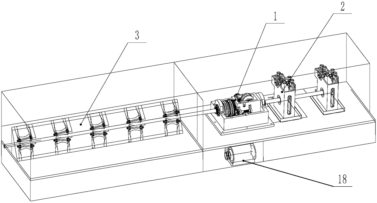
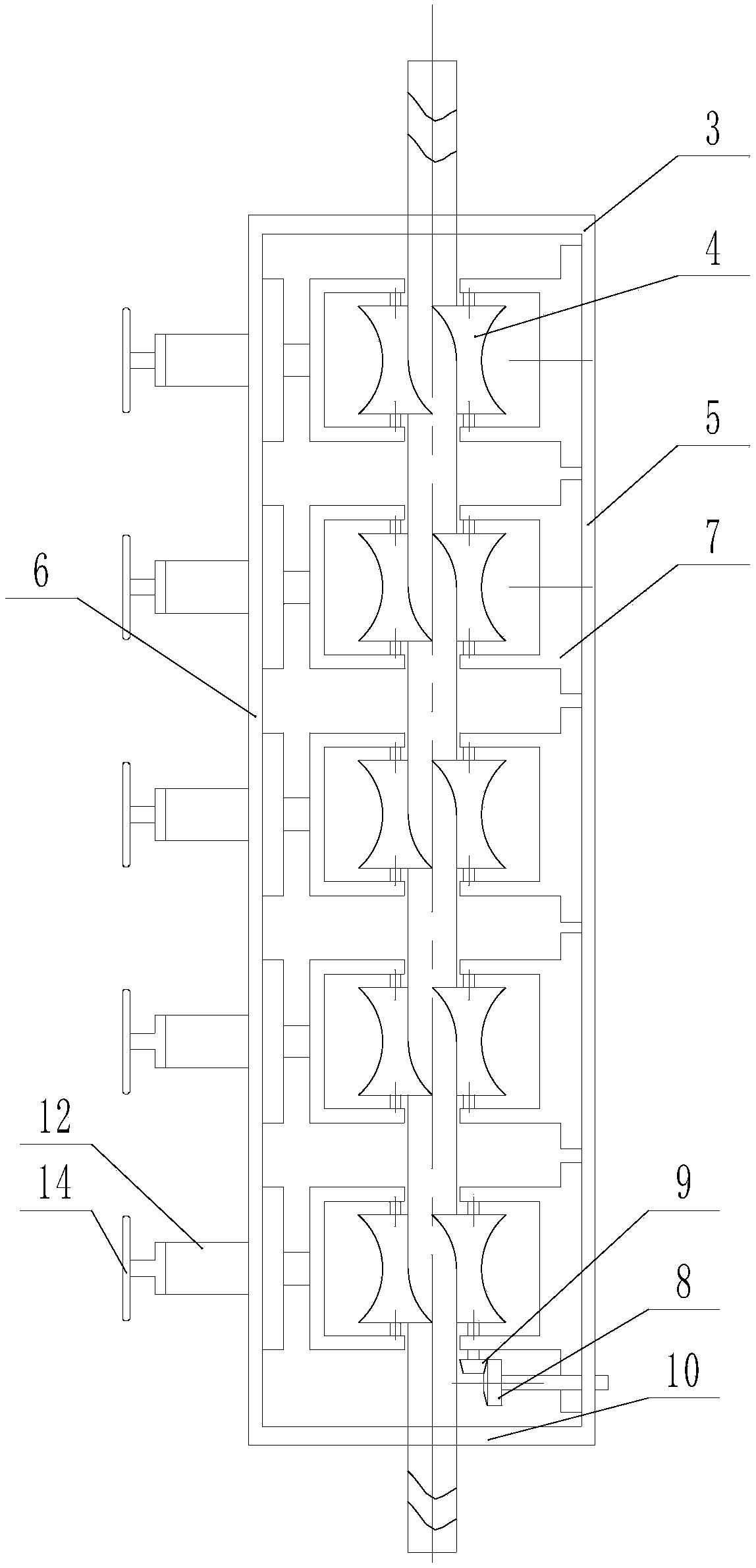
[0050] A steel pipe surface defect detection system, including a base plate, which is provided with a steel pipe transmission device 1 for driving the steel pipe to move along the axis direction and a steel pipe flaw detection device 2 arranged on the steel pipe movement path, and also includes a steel pipe feeding device set on the bottom plate Straightening device 3, steel pipe feeding The straightening device 3 is arranged at the feeding end of the steel pipe transmission device and is used for straightening the steel pipe.

[0051] In this way, the steel pipe is straightened first and then the material is fed for flaw detection, which can better avoid the influence of the straightness o...


PUM


Abstract

A flaw detection structure for steel pipe surface defect detection is disclosed. The structure includes a steel pipe transmission device for driving a steel pipe to move along an axial direction and asteel pipe flaw detection device disposed on the movement path of the steel pipe. The structure is characterized in that the steel pipe flaw detection device includes a detection tank; side plates atfront and rear sides, of the detection tank, in the direction of forward movement of the steel pipe are provided with a through hole respectively; a set of flaw detection mechanism is mounted on eachof the front and rear side plates of the detection tank; the flaw detection mechanisms have probes in the detection tank for flaw detection; the probes for flaw detection are fixed to the lower endsof adjusting bars vertically arranged; the upper ends of the adjusting bars are mounted on the side plates of the detection tank; and the probes of the two flaw detection mechanisms are at two sides of a steel pipe forward movement path and face the steel pipe forward movement path. The flaw detection structure has advantages of simple structure, and capability of improving flaw detection area andefficiency, avoiding detection leakage and improving flaw detection reliability.

Description

technical field [0001] The invention relates to a steel pipe surface defect detection device; in particular, it relates to a steel pipe surface defect detection flaw detection part structure. Background technique [0002] Steel pipe is an important steel material widely used. Due to various factors in the production process of steel pipe, defects such as longitudinal cracks, transverse cracks, folding, and delamination often exist on the steel pipe wall. If the steel pipe is defective, it will break during use and cause accidents, and even cause serious consequences, which may cause major economic losses or even casualties. For this reason, steel pipes for important purposes require complete non-destructive testing equipment to conduct online flaw detection on steel pipes. To ensure the quality of steel pipes leaving the factory, the existing flaw detection methods mainly include ultrasonic flaw detection and eddy current flaw detection inspection methods. The existing stee...

Claims


Application Information

Patent Timeline
Patent Type & Authority Applications(China)
IPC IPC(8): G01N29/27G01N27/90G01N29/04
CPCG01N27/90G01N27/9026G01N29/04G01N29/041G01N29/27G01N2291/0234G01N2291/0289
Inventor 吴建军赵伟周红波
Owner 宝武特冶航研科技有限公司
Why Eureka
Try Eureka