F-theta lens for laser processing

A laser processing and lens technology, applied in the optical field, can solve problems such as large distortion, small field of view, and large telecentricity, and achieve the effects of reducing measurement error, small distortion, and suppression of laser spot deformation

Inactive Publication Date: 2019-03-05
SHANGHAI MICRO ELECTRONICS EQUIP (GRP) CO LTD
View PDF0 Cites 4 Cited by
  • Summary
  • Abstract
  • Description
  • Claims
  • Application Information

AI Technical Summary

Problems solved by technology

[0005] The purpose of the present invention is to provide a kind of F-theta lens that is used for laser processing, for improving the F-theta lens field of view that exists in the prior art, telecentricity is big and distortion big problem

Method used


Image

  • F-theta lens for laser processing
  • F-theta lens for laser processing
  • F-theta lens for laser processing

Examples


Embodiment 2

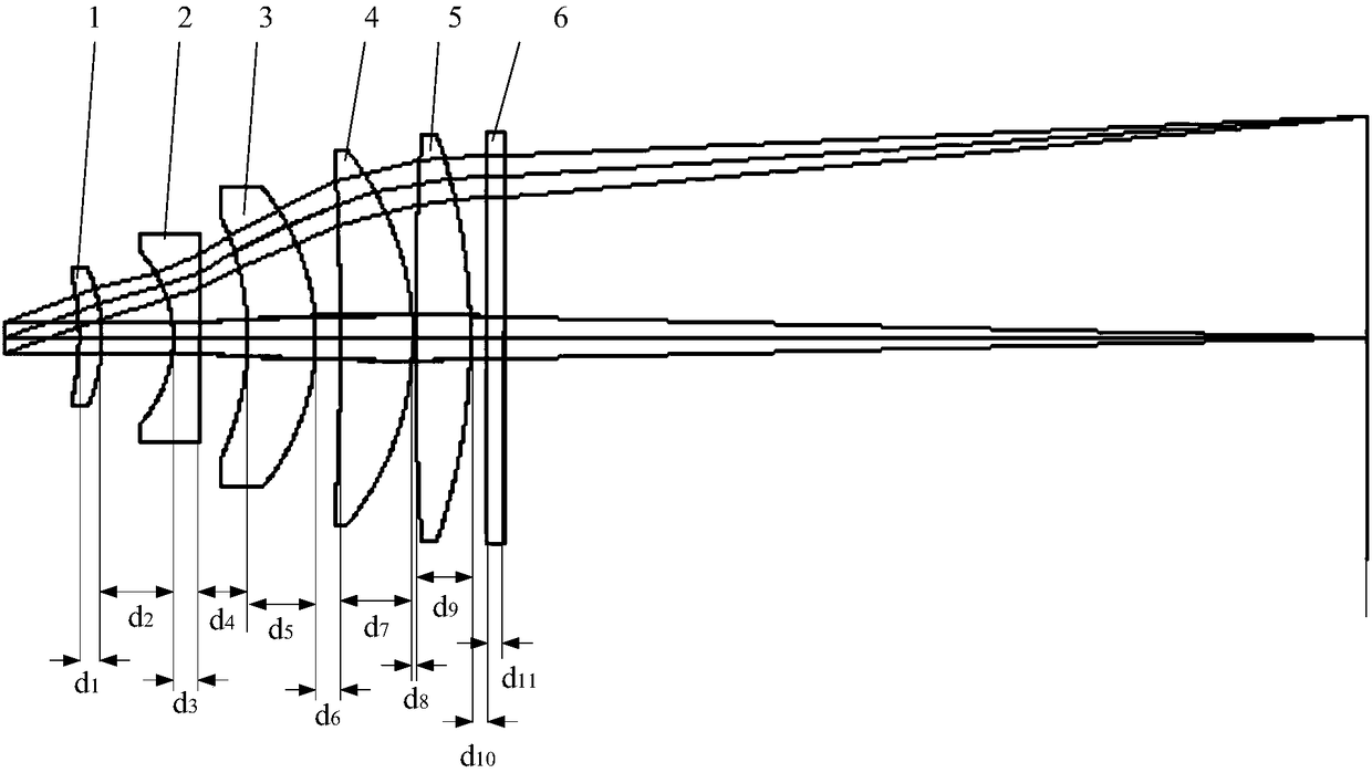
[0056] see Figure 4 , Figure 4 Schematic diagram of the structure of the F-theta lens provided for the second embodiment of the present invention, the F-theta lens includes: a first lens 1, a second lens 2, a third lens 3, a fourth lens 4, a fifth lens 5 and Protective window 6; Wherein the first lens 1 has positive refraction power; The second lens 2 has negative refraction power; The third lens 3 has positive refraction power; The fourth lens 4 has positive refraction power; The fifth lens 5 has positive refraction power degree; the protective window 6 is used to prevent the internal optical elements of the lens group from being affected by external dust and stray light, so the protective window 6 is a plane lens and does not have positive or negative refractive power.

[0057] Preferably, the focal length of each of the lenses and the total focal length of the F-theta lens satisfy the following relationship:

[0058] f1 / f=1.26

[0059] f2 / f=-0.435

[0060] f3 / f=2.25 ...


PUM


Abstract

The invention provides an F-theta lens for laser processing. The F-theta lens comprises a first lens with positive focal power, a second lens with negative focal power, a third lens with positive focal power, a fourth lens with positive focal power and a fifth lens with positive focal power. The F-theta lens is enabled to have the characteristics of large field of view, low telecentricity and small distortion through optimizing the mirror surface curvature of the lenses, the measurement error of light spots in the horizontal direction during laser processing is effectively reduced, and the distortion of laser spots within the scanning field of view range is well suppressed.

Description

technical field [0001] The invention belongs to the field of optical technology and relates to an F-theta lens for laser processing. Background technique [0002] F-theta mirrors are often used for field flattening and beam focusing, focusing the incident laser beam into a flat image field at an angle of + / -θ relative to the optical axis of the F-theta objective lens In this scanning angle area, the ratio of the scanning angle to the distance from the incident point of the laser beam to the optical axis in the image field follows a linear function. [0003] Due to the wavelength-dependent refraction of the laser beam, these F-theta objectives are aligned to the wavelength of the processing laser beam used in order to obtain a high focus quality when the laser beam passes through it, i.e. for such The objective is calculated such that, for an image field of a predetermined size at a predetermined wavelength and a predetermined laser beam diameter, within an allowable tempera...

Claims


Application Information

Patent Timeline
Patent Type & Authority Applications(China)
IPC IPC(8): G02B13/00
Inventor 孙建超
Owner SHANGHAI MICRO ELECTRONICS EQUIP (GRP) CO LTD
Why Eureka
Try Eureka