Bi-telecentric camera lens based on machine vision

A bi-telecentric lens and machine vision technology, applied in the direction of instruments, optical components, optics, etc., can solve the problem that the performance of the lens is easily affected by environmental factors such as temperature, it is difficult to ensure the consistency of measurement conditions, and the measurement range of the bi-telecentric lens Limited problems, to achieve the effect of ensuring the consistency of measurement conditions, low distortion, and low telecentricity

Active Publication Date: 2017-03-08
舜宇光学(中山)有限公司
View PDF10 Cites 13 Cited by
  • Summary
  • Abstract
  • Description
  • Claims
  • Application Information

AI Technical Summary

Problems solved by technology

[0003] Most of the existing bi-telecentric lenses have a limited measurement range, low magnification of the object image, and the performance of the lens is easily affected by environmental factors such as temperature
[0004] In machine vision measurement, when measuring the same part with different magnifications, it is necessary to replace the lens and recalibrate the position. This process not only affects the work efficiency, but also because it is difficult to ensure the consistency of the measurement conditions, the measurement data cannot be compared with the previous ones. data analysis

Method used


Image

  • Bi-telecentric camera lens based on machine vision
  • Bi-telecentric camera lens based on machine vision
  • Bi-telecentric camera lens based on machine vision

Examples


no. 1 example

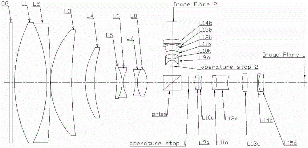
[0066] see figure 1 , is a structural diagram of the dual-magnification bi-telecentric lens of the present invention, and the present invention will be described in detail below with the help of drawings and charts. This bi-telecentric lens based on machine vision is characterized by setting protective glass, lens front group, transflective device, diaphragm, first lens rear group for low magnification measurement and high The second lens rear group for magnification measurement; the lens front group includes eight lenses: the first lens L1, the second lens L2, the third lens L3, the fourth lens L4, and the fifth lens L5 are arranged in sequence from left to right , the sixth lens L6, the seventh lens L7, and the eighth lens L8; wherein, the first lens L1 and the second lens L2 form a double cement and the cemented surface is bent toward the object plane, and the third lens L3 and the fourth lens L4 are both curved Moon-shaped and bent towards the diaphragm, the fifth lens L5...

Embodiment 2

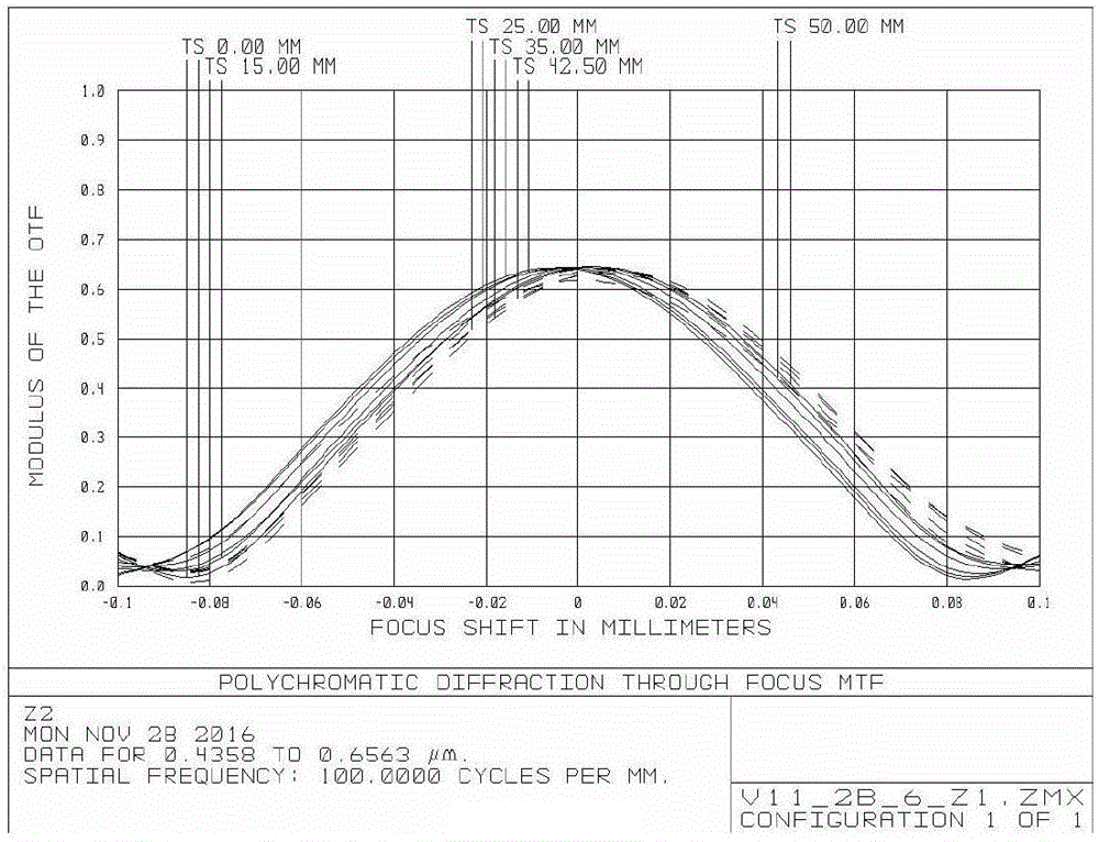
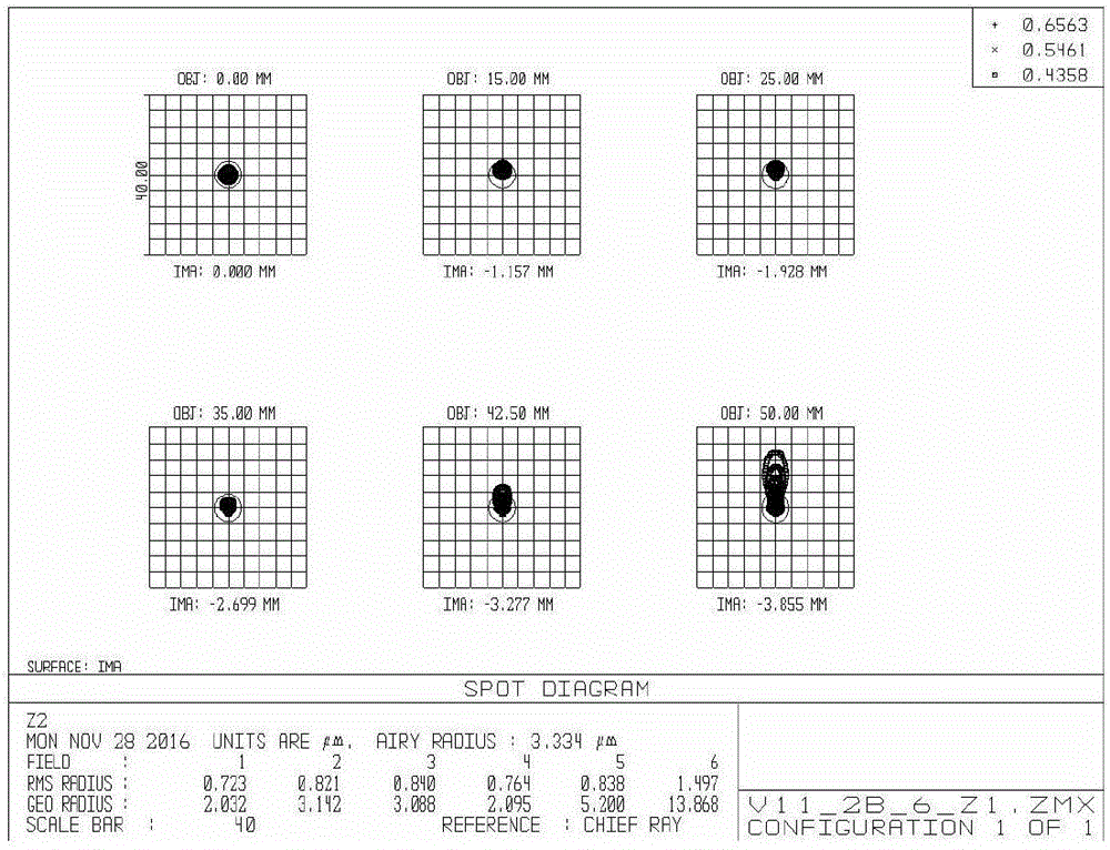
[0101] The preferred parameter table of Embodiment 2 is as follows: Table 7 to Table 9 are high magnification telecentric optical path parameter values, and Table 10 to Table 12 are low magnification telecentric optical path parameter values. Figure 16-Figure 27 It is an illustration of the lens analysis and temperature characteristics of the second embodiment. It can be seen from the graph that, under the condition of ensuring low telecentricity, the lens meets the requirements in terms of resolution, distortion, temperature characteristics and the like.

[0102] Table Seven

[0103] field FOV (degree) CRA (degree) 0.1 0.0006 0.007 0.2 0.0009 0.011 0.3 0.0016 0.016 0.4 0.0024 0.022 0.5 0.0033 0.035 0.6 0.0039 0.041 0.7 0.0045 0.045 0.8 0.0050 0.035 0.9 0.0052 0.023 1 0.0055 0.017

[0104] table eight

[0105] G12 / f4 G56 / G78 G9b / f11b G12b / G14b 0.55 -0.75 -1.55 2.52

[0...


PUM


Abstract

A bi-telecentric camera lens based on machine vision comprises, in sequence from left to right, protective glass, a front lens group, a half-transmitting and half-reflecting device, a diaphragm, a first rear lens group for low-magnification measurement, and a second rear lens group for high-magnification measurement. The front lens group includes eight lenses, which are a first lens, a second lens, a third lens, a fourth lens, a fifth lens, a sixth lens, a seventh lens and an eighth lens in sequence from left to right. The front lens group forms a bi-telecentric light path together with the first rear lens group and the second rear lens group. The first lens and the second lens constitute a doublet, and the agglutination surface is bent towards the object plane. The third lens and the fourth lens are crescent-shaped and bent towards the diaphragm. The fifth lens and the sixth lens constitute a doublet which has negative focal power. The seventh lens and the eighth lens constitute a doublet, and the agglutination surface is bent towards the diaphragm. The bi-telecentric camera lens can be connected with two CCDs or CMOSs at the same time to measure an object at different magnifications.

Description

technical field [0001] The invention belongs to the technical field of optical system and device design, in particular to a bi-telecentric lens based on machine vision. Background technique [0002] Industrial lenses are very important optical components in the field of machine vision. Due to the different magnifications at different object distances, traditional industrial lenses have large perspective errors, and it is difficult to meet the high-precision measurement requirements. The telecentric lens can eliminate this perspective error caused by different object distances, and the image magnification remains unchanged within a certain object distance range. [0003] Most of the existing bi-telecentric lenses have a limited measurement range, low magnification of the object image, and the performance of the lens is easily affected by environmental factors such as temperature. [0004] In machine vision measurement, when measuring the same part with different magnificati...

Claims


Application Information

Patent Timeline
Patent Type & Authority Applications(China)
IPC IPC(8): G02B13/22G02B1/00
CPCG02B13/22G02B1/00
Inventor 白兴安张德伦付湘发梁伟朝贺保丁蓝岚周静张鸿佳
Owner 舜宇光学(中山)有限公司
Why Eureka
Try Eureka