Novel optical cable security system with 3D overhead crossing protection

A security system and optical cable technology, applied in the direction of anti-theft alarms, anti-theft alarm mechanical activation, and alarms by breaking/disturbing the straightened rope/metal wire, etc., can solve the problems of being easily noticed and misleading security personnel. , to achieve the effect of improving concealment and anti-destructive ability, improving reliability and accuracy

Inactive Publication Date: 2019-03-05
苏州攀星光电科技有限公司
View PDF0 Cites 5 Cited by
  • Summary
  • Abstract
  • Description
  • Claims
  • Application Information

AI Technical Summary

Problems solved by technology

At the same time, the above-mentioned installation method is easy to be noticed by people, so that the intruder tries to avoid or be destroyed
Intruders may intentionally trigger the alarm and then leave quickly to mislead the security personnel, or destroy the fiber optic cable first and leave, then invade again before the fiber optic cable is repaired, or simply intrude by digging tunnels directly, completely avoiding all intrusion alarm systems on the ground

Method used


Image

  • Novel optical cable security system with 3D overhead crossing protection
  • Novel optical cable security system with 3D overhead crossing protection

Examples


Embodiment 1

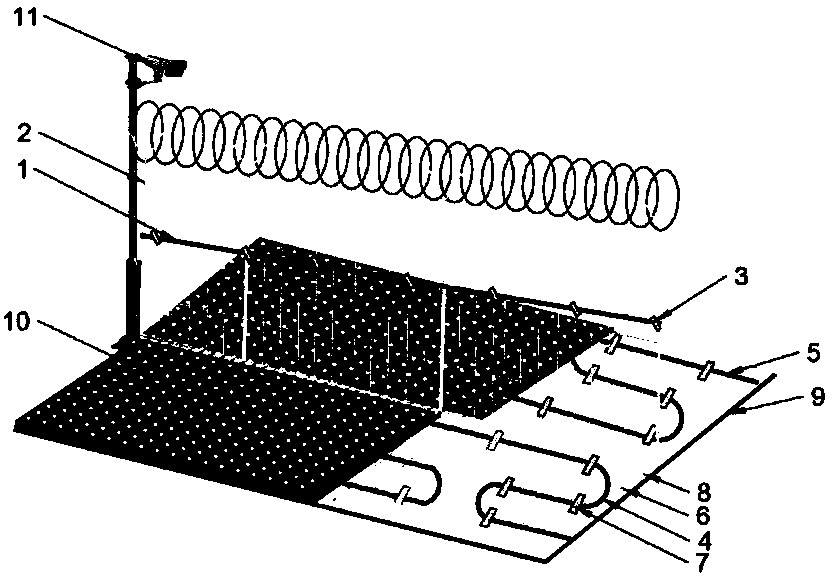
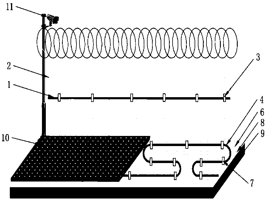
[0030] Such as figure 1 and figure 2 As shown, a new type of optical cable security system for three-dimensional cross protection, which is used for the intrusion alarm of the perimeter fence, is characterized in that: the #1 induction optical cable (1) is bound to the fence (2) with a cable tie (3); #2 sensing optical cable (4) and #3 sensing optical cable (5) are buried in the ground on both sides of the fence (2) in an Ω shape respectively, with a geogrid (6) underneath it, and the buried sensing optical cable (4 , 5) Fix it on the geogrid (6) with cable ties (7), between the geogrid (6) and the soil layer (9) is a gravel layer (8); above the buried optical cable (4, 5) Cover it with a layer of turf (10) to increase concealment; #1~#3 sense vibration signals generated by environmental changes near the optical cables (1, 4, 5), modulate the laser signals in the optical fibers, and modulate the optical The signal is transmitted back to the signal analysis and identificatio...

Embodiment 2

[0032] Embodiment two is slightly different from embodiment one, and its main difference is:

[0033] Only keep the #1 sensor cable on the fence and the #3 buried sensor cable outside the fence, and don’t install the #2 sensor cable on the inside. This method is suitable for detecting intrusions from outside to inside, such as airports.

Embodiment 3

[0035] Embodiment three is slightly different from embodiment one, and its main difference is:

[0036] Only the #1 sensor cable on the fence and the #2 buried sensor cable inside the fence are kept, and the #3 sensor cable on the outside is not installed. This method is suitable for detecting movement from the inside to the outside, such as jailbreak.


PUM


Abstract

The invention discloses a novel optical cable security system with 3D overhead crossing protection, and belongs to the technical field of monitoring. The system comprises three sensing optical cablesand a circumferential fence, one sensing optical cable is fixed on the fence via a band and arranged along the direction parallel with the fence, and the other two optical cables are burned underground inside and outside the fence respectively. A computer crossing identification algorithm is used to compare and confirm signals generated by the tree optical cables, the system sensitivity is improved greatly, the false alarm rate of the system is reduced greatly, and the reliability is substantially improved substantially compared with a routine optical cable fence. The system can identify intrusion manners including climbing the fence and underground digging, and is highly resistant to severe weather as storm. The system is suitable for circumference intrusion alarm of different facilitiesin places with higher security requirements as an airport, prison and military base.

Description

technical field [0001] The invention belongs to the technical field of monitoring, and in particular relates to a novel optical cable security system for three-dimensional intersection protection. Background technique [0002] One of the main tasks of the security protection monitoring system is to identify various perimeter intrusion events in real time. [0003] The fiber optic cable fence represents the most advanced security technology at present. Through the sensing fiber optic cable, the perception of abnormal perturbation around the fence is used for pattern recognition, so as to determine whether there is an intrusion and accurately locate the location of the intrusion. The sensing optical cable is a sensor for sensing the presence of intruders or sensing whether the fence is damaged. The sensing optical cable is connected to the signal receiver, and outputs the collected signal to the signal receiver in time. By analyzing the signal characteristics, the computer ju...

Claims


Application Information

Patent Timeline
Patent Type & Authority Applications(China)
IPC IPC(8): G08B13/12
CPCG08B13/124
Inventor 不公告发明人
Owner 苏州攀星光电科技有限公司
Why Eureka
Try Eureka