
Antenna azimuth angle optimization method and device based on MR positioning data

A technology of antenna azimuth and positioning data, which is applied to antennas, wireless communications, electrical components, etc., can solve problems such as the inability to timely and proactively discover antenna optimization requirements, uneven technical capabilities and sense of responsibility of maintenance personnel, and achieve The effect of low cost and high efficiency

Inactive Publication Date: 2019-03-05
CHINA MOBILE GROUP ZHEJIANG +1
View PDF5 Cites 14 Cited by
  • Summary
  • Abstract
  • Description
  • Claims
  • Application Information

AI Technical Summary

Problems solved by technology

[0006] ① The accuracy of antenna basic data maintenance: From the beginning of network access to the daily stable operation of the antenna, there will be frequent optimization and adjustment due to network requirements. Uneven, there are great challenges in the timeliness and accuracy of antenna data updates
[0007] ②Unable to timely and proactively discover antenna optimization requirements: wireless networks will constantly change with users and wireless environments, and the current antenna optimization cannot reflect the optimization requirements of traffic model changes caused by user changes, such as the impact of new buildings , user movement, etc.

Method used


Image

  • Antenna azimuth angle optimization method and device based on MR positioning data
  • Antenna azimuth angle optimization method and device based on MR positioning data
  • Antenna azimuth angle optimization method and device based on MR positioning data

Examples


Embodiment Construction

[0045] The specific implementation manners of the present invention will be further described in detail below in conjunction with the accompanying drawings and embodiments. The following examples are used to illustrate the present invention, but are not intended to limit the scope of the present invention.

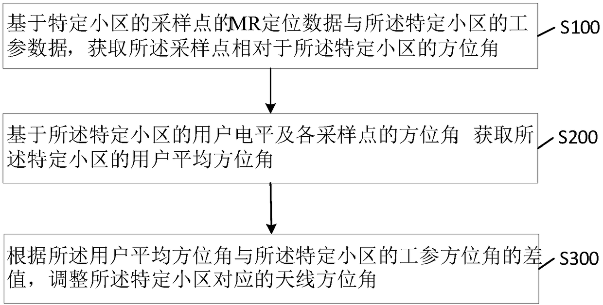
[0046] Based on the current status quo, in order to improve the accuracy of antenna asset management data and actively discover antenna optimization requirements, the embodiment of the present invention provides an antenna azimuth optimization method based on MR positioning data, such as figure 1 shown, including:

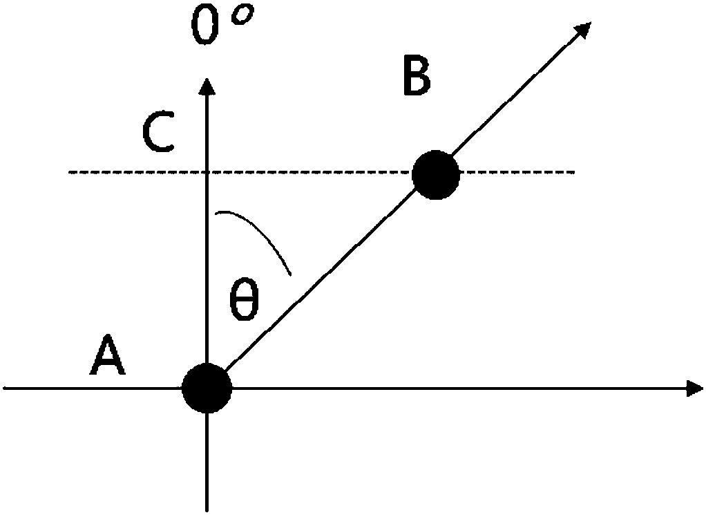
[0047] S100. Acquire an azimuth of the sampling point relative to the specific cell based on the MR positioning data of the sampling point of the specific cell and the industrial parameter data of the specific cell;

[0048] Specifically, the MR positioning data includes: the unique number of the cell, the base station number, the cell number, the longitude of...


PUM


Abstract

The invention provides an antenna azimuth angle optimization method and device based on MR positioning data. The antenna azimuth angle optimization method based on the MR positioning data comprises the following steps: obtaining an azimuth angle of a sampling point with respect to a specific cell based on the MR positioning data of the sampling point of the specific cell and work parameter data ofthe specific cell; obtaining a user average azimuth angle of the specific cell based on user levels of the specific cell and the azimuth angle of each sampling point; and adjusting an antenna azimuthangle corresponding to the specific cell according to a difference value between the user average azimuth angle and the work parameter azimuth angle of the specific cell. The invention completes rationality analysis of the antenna azimuth angle based on the sampling point on the basis of the accurate MR positioning data, and compares the existing network work parameter data and checks the deviation, so as to carry out fine optimization of the antenna azimuth angle; compared with the traditional antenna feeder optimization relying on the Davi field census, the antenna azimuth angle optimization method and device based on the MR positioning data has higher efficiency and less cost, and can timely discover the demand for antenna feeder optimization due to the change of a traffic model; therefore, cost reduction and efficiency increase are truly realized.

Description

technical field [0001] The present invention relates to the technical field of antennas, and more specifically, to an antenna azimuth optimization method and equipment based on MR positioning data. Background technique [0002] Antenna azimuth optimization is a basic optimization work in wireless network optimization work. Accurate antenna feeder parameter information is the basis for network index analysis such as performance and drive test. The current antenna optimization and maintenance work is mainly divided into two parts: [0003] Actively optimize maintenance: Daily maintenance of antenna feeder data is mainly carried out by the maintenance agent according to the inspection plan, using tools such as antenna attitude meter and level meter to measure. Anomalies are found, and then asset management data maintenance is carried out; or provincial and municipal companies initiate special censuses due to work needs, such as the "antenna engineer operation" launched by Zhej...

Claims


Application Information

Patent Timeline
Patent Type & Authority Applications(China)
IPC IPC(8): H04W24/02H04W64/00H01Q3/00
CPCH01Q3/00H04W24/02H04W64/006
Inventor 姜奇华赵锦松童海生吴剑平彭陈发范永升马骢艾华杨占军李海振丁霞俊谈国泉
Owner CHINA MOBILE GROUP ZHEJIANG
Learn More