Stamping forming process to replace the stamping station of profile machining

A stamping forming and machining technology, applied in the stamping and forming field, can solve the problems of slow processing speed, high cost, and reduced product production efficiency of machining centers, and achieve the effect of saving costs, improving production efficiency and facilitating promotion.

Active Publication Date: 2020-06-30
天津市津兆机电开发有限公司
View PDF5 Cites 0 Cited by
  • Summary
  • Abstract
  • Description
  • Claims
  • Application Information

AI Technical Summary

Problems solved by technology

[0003] The lower end of this type of material often has a certain area of ​​steps, and the thickness of the product needs to be punched step by step in the stamping process; the traditional process is to use numerical control processing equipment to process the thinner part of the product in the stamping process to achieve the product thickness. Here, the shape, size and accuracy are required; however, this method needs to make a set of fixtures in advance to make the product correctly fixed on the machining center table; in addition, it is necessary to transport the stamped product to the machining area in advance during the production process. Milling, after the processing is completed, the product is transported back to the stamping area for the subsequent bending process; in this traditional process, not only the product needs to be turned over, transported, stored and clamped several times, but also the processing speed of the machining center Slow, the processing program needs to be made in advance, which greatly reduces the production efficiency of the product; in addition, the cost is also high

Method used


Image

  • Stamping forming process to replace the stamping station of profile machining
  • Stamping forming process to replace the stamping station of profile machining
  • Stamping forming process to replace the stamping station of profile machining

Examples


Embodiment Construction

[0029] In order to make the object, technical solution and advantages of the present invention more clear, the present invention will be further described in detail below in conjunction with the examples. It should be understood that the specific embodiments described here are only used to explain the present invention, not to limit the present invention.

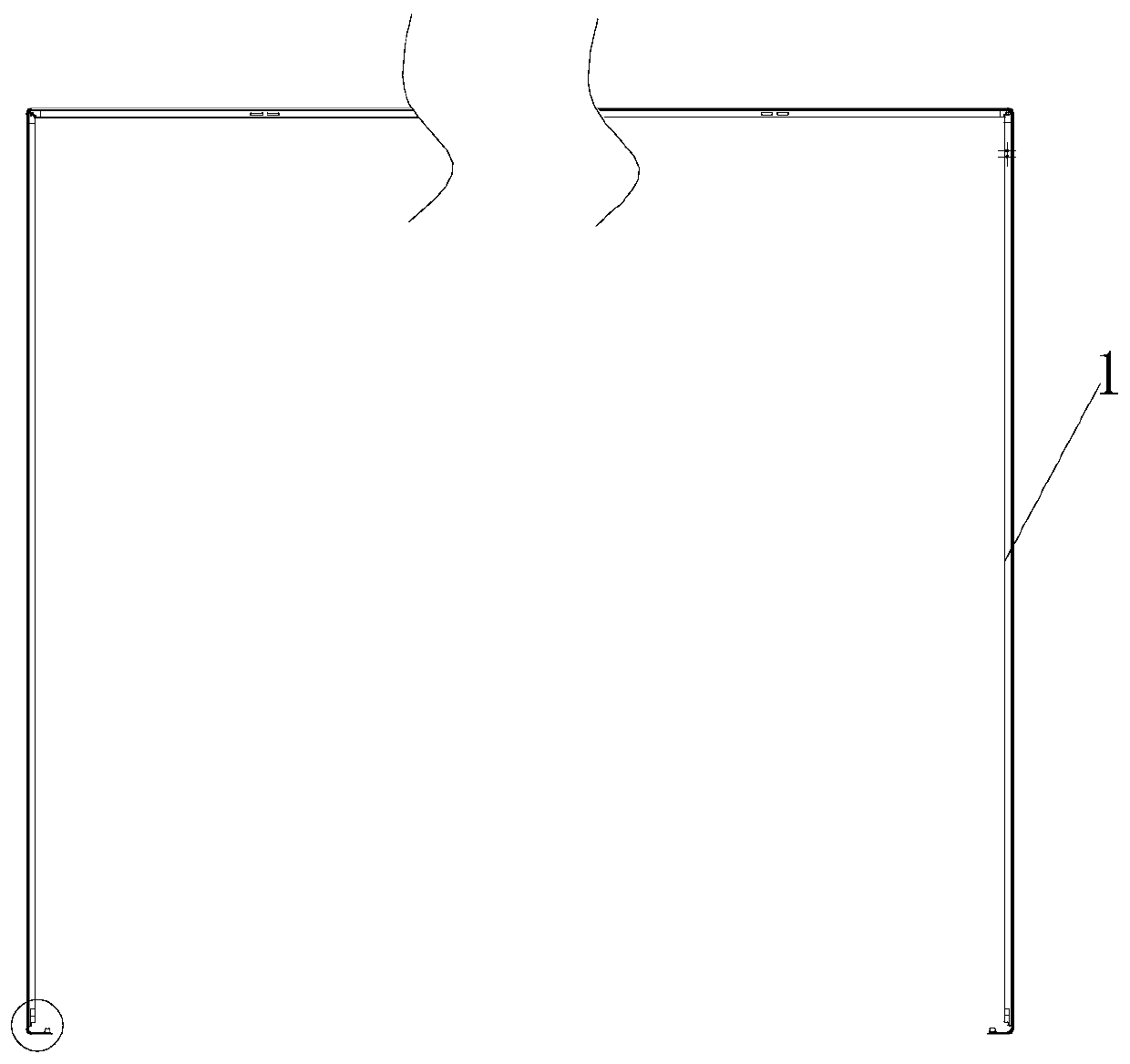
[0030] In this embodiment, taking the TV frame 1 as an example, the stamping station and the stamping forming process for replacing the profile machining are described.

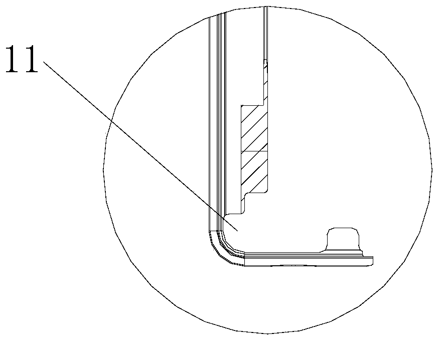
[0031] figure 1 Shown is the TV frame 1 to be processed, and the TV frame 1 is punched and thinned on the basis of the strip profile 2, and then bent; figure 2 The middle shaded area is the area of ​​the product that needs to be thinned; the current thinned figure 2 The middle shadow part requires the combination of stamping equipment and CNC processing equipment, which is inefficient and expensive;

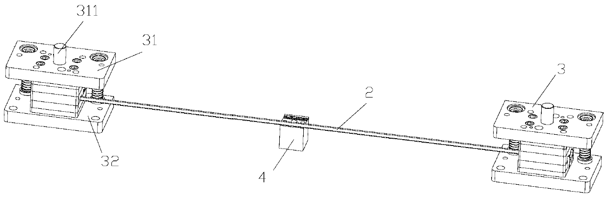
[0032] In view of the above technical problems, th...


PUM


Abstract

The invention discloses a stamping station replacing proximate matter machining, and a stamping and forming process, and belongs to the technical field of stamping and forming. The stamping station comprises a profiling station and a trimming station, wherein the profiling station and the trimming station are simultaneously arranged on one same technological equipment. The stamping station comprises a profiling punch arranged on a fixed plate and a profiling concave die arranged on a concave die plate, wherein positioning blocks I are arranged on two sides of the profiling concave die along the length direction of a strip-shaped proximate matter; an L-shaped positioning structure I is arranged at the position, corresponding to the profiling concave die, on the concave die plate; the trimming station comprises a trimming punch arranged on the fixed plate and a trimming concave die arranged on the concave die plate; positioning blocks II are arranged on two sides of the trimming concavedie along the length direction of the strip-shaped proximate matter; an L-shaped positioning structure II is arranged at the position, corresponding to the trimming concave die, on the concave die plate. According to the stamping station replacing proximate matter machining, and the stamping and forming process provided by the invention, only an original operational path needs to be enlarged, sothat the cost is saved; and no excessive turnover, transportation and storage is produced, so that the production efficiency is greatly improved.

Description

technical field [0001] The invention belongs to the technical field of punching and forming, and in particular relates to a punching and forming process which replaces the punching station of profile machining. Background technique [0002] Profiles are objects with certain geometric shapes made of iron or steel and materials with certain strength and toughness (such as plastic, aluminum, glass fiber, etc.) through rolling, extrusion, casting and other processes. At present, strip-shaped profiles are widely used in the market. For example, the outer frames of TVs and computers are made of strip profiles. [0003] The lower end of this type of material often has a certain area of ​​steps, and the thickness of the product needs to be punched step by step in the stamping process; the traditional process is to use numerical control processing equipment to process the thinner part of the product in the stamping process to achieve the product thickness. Here, the shape, size and ...

Claims


Application Information

Patent Timeline
Patent Type & Authority Patents(China)
IPC IPC(8): B21D22/02B21D35/00
CPCB21D22/02B21D35/002
Inventor 贾楠周峰张占朋白广江
Owner 天津市津兆机电开发有限公司
Why Eureka
Try Eureka