Pneumatic type tool changing device

A tool change device, pneumatic technology, applied in the field of pneumatic tool change device, can solve the problems of unable to lock the tool, wear of the tool and movable pin, and affect the speed of tool change, so as to achieve high equipment safety operation coefficient and avoid spring aging , The effect of fast tool change

Pending Publication Date: 2019-03-08
SUZHOU VOCATIONAL UNIV
View PDF8 Cites 2 Cited by
  • Summary
  • Abstract
  • Description
  • Claims
  • Application Information

AI Technical Summary

Problems solved by technology

This type of tool changer generally has the following defects during use: (1) When grabbing and releasing the knife, the tool will collide with the movable pin at the buckle edge, which will not only produce metal impact sounds, but also cause the tool to collide with the movable pin. The wear, deformation and damage of the tool should not be too fast, which will affect the tool change speed; (2) The tool is clamped and locked only by one movable pin. If the movable pin fails, it will not work normally, and the equipment is safe. The operating coefficient is not high; (3) The locking of the tool is realized by the spring pushing the locking pin. If the spring of the locking pin is aged or broken, resulting in insufficient elasticity, it is easy to cause the tool to be unable to be locked and the tool to fall

Method used


Image

  • Pneumatic type tool changing device
  • Pneumatic type tool changing device

Examples


Embodiment Construction

[0024] In order to have a further understanding of the purpose, structure, features, and functions of the present invention, the following detailed descriptions are provided in conjunction with the embodiments.

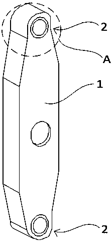
[0025] Please refer to figure 1 and figure 2 . A pneumatic tool changing device according to an embodiment of the present invention, such as figure 1 As shown, it includes the tool changing arm 1 and the tool changing hand 2. During the tool changing process, the tool changing arm 1 can rotate around the rotation axis at its center and move up and down. The two tool changing hands 2 are respectively located at the ends of the tool changing arm 1 At both ends, the tool changer 2 is used to hold the tool. Two ends of the tool changing arm 1 are respectively provided with a clamping hole, and a tool changing hand 2 is installed in the two clamping holes.

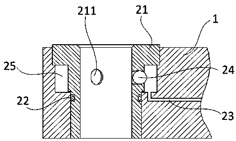
[0026] Such as figure 2 As shown, the tool changing hand 2 includes a clamping seat 21 , a sealing ring 22 , ...


PUM


Abstract

The invention provides a pneumatic type tool changing device. The pneumatic type tool changing device comprises a tool changing arm and tool changing hands. The tool changing arm is used for rotating,and the tool changing hands are used for clamping a cutting tool. Each tool changing hand comprises a clamping base, an elastic part, a piston, abutting parts and an electromagnet. Each clamping baseis installed on the tool changing arm, and a plurality of assembly holes are formed in the circumferential wall of each clamping base in a penetrating mode. The elastic part, the piston and the electromagnet of each tool changing hand are arranged on the corresponding clamping base in a sleeving mode, the position of each electromagnet relative to the corresponding piston is kept in a fixed state, and the two ends of each elastic part elastically abut against the corresponding electromagnet and the corresponding piston correspondingly. The multiple abutting parts are movably and correspondingly installed in the assembly holes formed in the clamping bases and abut against the pistons. By the adoption of the pneumatic type tool changing device, no collision happens in the tool changing process, the clamping operation of the cutting tool is accomplished by a plurality of parallel functional parts which are independent from each other, the safe operation coefficient is high, the locking mode is changed, and the tool falling phenomenon can be effectively avoided.

Description

technical field [0001] The invention relates to the field of tool change in machining centers, in particular to a pneumatic tool change device. Background technique [0002] The tool changer is an important part of the machining center, and its function is to exchange the tool on the spindle with the tool in the tool magazine to realize the function of automatic tool change. At present, the tool changer holding the tool in the tool changing device generally adopts the spring pin type clamping method, and the principle is to use the spring to push the movable pin and the locking pin to realize the clamping and locking of the tool. This type of tool changer generally has the following defects during use: (1) When grabbing and releasing the knife, the tool will collide with the movable pin at the buckle edge, which will not only produce metal impact sounds, but also cause the tool to collide with the movable pin. The wear, deformation and damage of the tool should not be too f...

Claims


Application Information

Patent Timeline
Patent Type & Authority Applications(China)
IPC IPC(8): B23Q3/155
CPCB23Q3/1554B23Q2003/155404
Inventor 黄海洋左斌
Owner SUZHOU VOCATIONAL UNIV
Why Eureka
Try Eureka