Marine profile buoy and control method thereof
A technology of ocean profile and control method, which is applied in the direction of buoys, special-purpose vessels, instruments, etc., can solve the problems of frequency solidification of detection, inability to achieve long-range parameter measurement and fine measurement, etc., achieve long underwater working time and realize fine Effect of Measurement and Velocity Measurement
- Summary
- Abstract
- Description
- Claims
- Application Information
AI Technical Summary
Problems solved by technology
Method used
Image
Examples
Embodiment 1
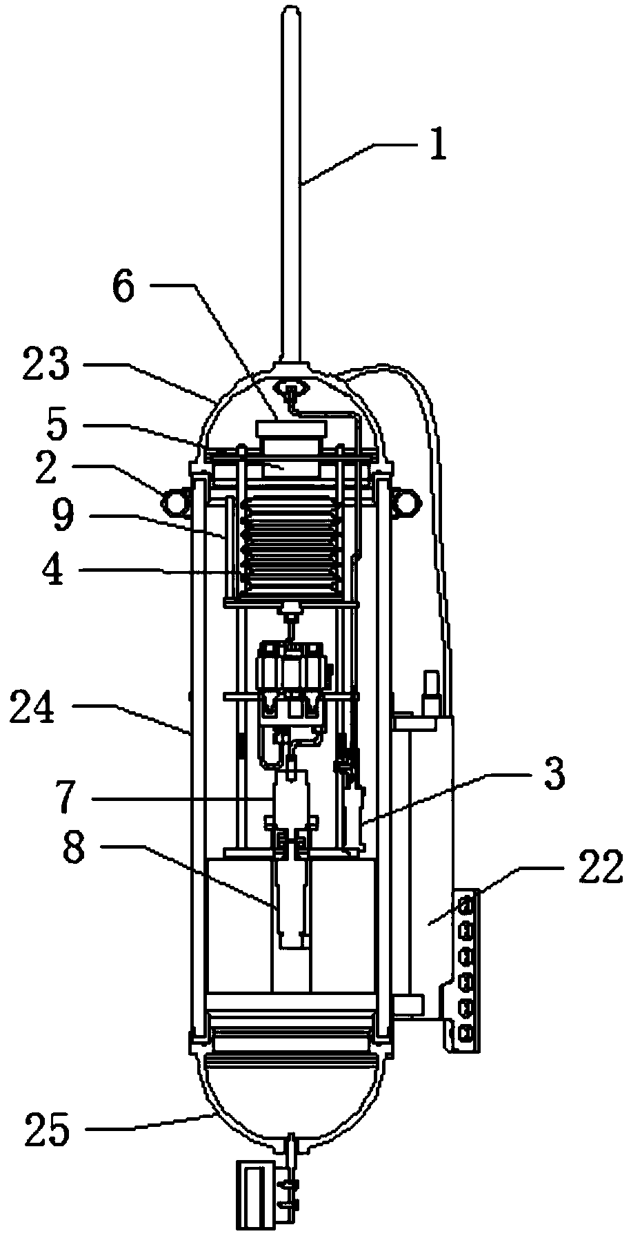
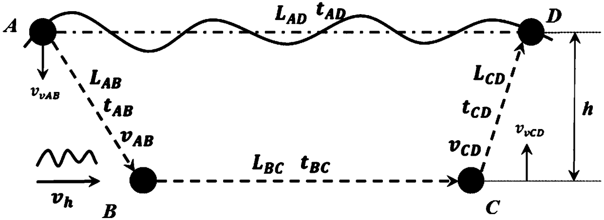
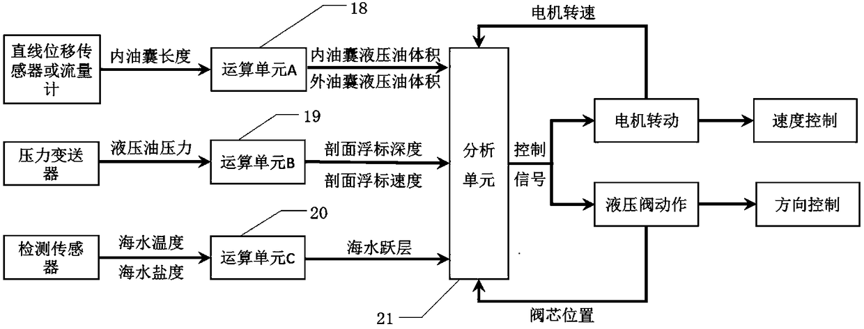
[0056] Such as Figure 1-6 As shown, an ocean profiling buoy comprising,
[0057] The housing, the housing is composed of an upper end cover 23, a cylinder body 24 and a lower end cover 25, and a sealing ring is arranged between the upper end cover 23, the lower end cover 25 and the cylinder body 24 to realize the purpose of sealing, and the housing is arranged as The three parts are easy to disassemble and easy to maintain. An outer oil bag 2 arranged outside the casing, specifically, the outer oil bag 2 is arranged on the outer wall of the upper part of the cylinder 24, and the outer oil bag 2 is arranged on the upper part of the cylinder 24 can overcome the problem of insufficient self-priming force of the plunger pump 7 . The outer oil bag 2 forms a ring around the periphery of the cylinder 24, and an inner oil bag 4 is arranged in the housing. Specifically, the inner oil bag 4 is arranged at the upper part of the cylinder 24, which can also compensate for the self-primi...
Embodiment 2
[0103] as attached Figure 5 As shown, this embodiment is a replacement for the linear displacement sensor 9 in Embodiment 1. Specifically, the linear displacement sensor 9 is replaced by a flow meter 14. The specific connection and oil circuit control are as follows:
[0104] The flowmeter 14 is installed between the outer oil bag 2 and the pressure transmitter 3 or in the pipeline between the inner oil bag 4 and the outer oil bag 2 .
[0105] When the profile buoy floats up, the solenoid valve B11 and solenoid valve C12 are closed (solenoid valve A10 and solenoid valve D13 are normally open), the motor 8 drives the plunger pump 7, and the oil in the inner oil bag 4 passes through the solenoid valve C12 and flows through the column in turn. The plug pump 7, solenoid valve B11, pressure transmitter 3 and flowmeter 14 enter the outer oil bag 2, the volume of the outer oil bag 2 increases, the buoyancy of the profile buoy increases, and the profile buoy rises.
[0106] When the...
Embodiment 3
[0110] as attached Figure 6 As shown, in this embodiment, the plunger pump 7 in the power unit in Embodiment 1 is replaced by a two-way gear pump 16, and a hydraulic booster 15 and a relief valve 17 are added to the hydraulic oil circuit. The road control is as follows:
[0111] The above-mentioned motor 8 is driven and connected with a bidirectional gear pump 16, and the two ends of the bidirectional gear pump 16 are respectively connected with a relief valve 17 and a check valve. The relief valve 17 can protect the hydraulic oil circuit from pressure in the hydraulic oil circuit. Too large to destroy the work of the entire power unit; the two ends of the two-way gear pump 16 are also connected with the inner oil bag 4 and the outer oil bag 2, and the hydraulic booster 15 is connected between the outer oil bag 2 and the two-way gear pump 16, and the two-way gear pump 16 and hydraulic booster 15 can solve the problem of insufficient self-priming force that plunger pump 7 exi...
PUM
 Abstract
Description
Claims
Application Information
 - R&D
- Intellectual Property
- Life Sciences
- Materials
- Tech Scout
- Unparalleled Data Quality
- Higher Quality Content
- 60% Fewer Hallucinations
Browse by: Latest US Patents, China's latest patents, Technical Efficacy Thesaurus, Application Domain, Technology Topic, Popular Technical Reports.
© 2025 PatSnap. All rights reserved.Legal|Privacy policy|Modern Slavery Act Transparency Statement|Sitemap|About US| Contact US: help@patsnap.com


